As an Amazon Associate, we earn from qualifying purchases. Some links on this site are affiliate links at no extra cost to you. Our recommendations are based on thorough research and editorial judgment.

Why Real-Time Monitoring Matters in Modern Welding Systems
You’ve just inspected a batch of welded parts and found intermittent porosity and inconsistent bead profiles, but you can’t pinpoint when or why the defects started. You’re stuck asking which welds to rework, whether the process drifted, and how to prevent the same rejects tomorrow. Most teams react after failures, trusting human inspection and periodic sampling instead of continuous oversight.
This introduction will show you how real‑time welding monitoring catches faults as they form, how cameras, current and acoustic sensors detect arc drift, porosity, and heat spikes, and how logged data plus automatic parameter adjustments cut rework and downtime. You’ll also learn practical deployment steps, sensor choices, and the measurable outcomes: fewer rejects, faster troubleshooting, and traceable records. It’s easier than it sounds.
Key Takeaways
Here’s what actually happens when you monitor welding in real time: you catch small problems before they become big, expensive ones.
You may be interested


– You stop defects and rework by detecting drifting arcs, porosity, and parameter spikes as they happen so you can correct them immediately. Example: when a MIG weld’s arc voltage drifts 5–10% over 2 seconds, an automatic alert pauses the weld and prompts you to adjust shielding gas flow or torch angle.
Maintain consistent weld quality through closed‑loop adjustments that act in milliseconds. For example, a controller that adjusts wire feed speed and voltage every 10–20 ms keeps bead shape steady during a long, curved seam. Fix it fast.
– You reduce downtime and surprise shutdowns by setting automated pause thresholds and enabling remote operator intervention when limits are exceeded. Example: set a current spike threshold at ±8%; if reached, the system stops and sends a 10‑second video clip plus telemetry to your phone so you can decide to resume or inspect.
Before you rely on inspection alone, log events and keep pre‑event data to cut inspection time and scrap rates. Steps:
- Configure the system to store the last 5–10 seconds of data for every triggered event.
- Tag each event with operator ID, part number, and weld parameters.
- Review only tagged events during QA checks.
Example: a 6‑second pre‑event waveform shows a torch knock 3 cm off target, so you replace a worn liner instead of scrapping the part.
– You improve safety and help operators learn by using live feeds, training simulators, and ergonomics‑driven sensors that reduce strain. Example: a headset camera plus force sensors shows you that a 20° torch tilt causes wrist strain and inconsistent penetration, so you retrain the operator with a simulator session lasting 15–20 minutes.
Each paragraph above highlights one key action you can take and gives a specific example you can use on the shop floor.
How Real‑Time Welding Monitoring Works
Here’s what actually happens when you monitor a weld in real time: it matters because catching problems as they start saves hours of rework or scrapped parts.
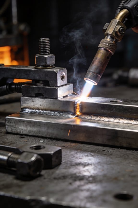
Often you begin with a simple loop: sensors and cameras pick up data from the arc, the torch, and the weld pool, that information goes to a processor which analyzes it, and then control actions or alerts are issued if something looks off. In a small fabrication shop you might mount a near‑infrared camera 300 mm from the torch and a current sensor on the feeder; that setup can detect a drifting arc within one weld pass. Use a 1 ms sampling rate for current and a 30–60 fps camera for reliable timing.
Before you adjust anything, here’s why closed‑loop control matters: keeping the weld consistent reduces defects and saves time.
Closed‑loop control means measurements feed back continuously to change voltage, wire feed speed, or torch position. Do this in three steps:
- Measure: sample current, voltage, and pool images every 1–10 ms.
- Decide: run a simple rule or model in under 50 ms to determine an adjustment.
- Act: change wire speed by up to ±10% or tweak torch position by a few millimeters.
A robotic welder in an automotive jig that shifts slightly during a run can maintain bead shape by adjusting torch position by 2–3 mm on the fly.
Think of signal fusion like combining clues from witnesses to get the full story: it matters because one sensor alone can lie.
Signal fusion combines inputs such as current traces, arc voltage, and visual cues into a single, clearer picture. Do this with a simple weighted average or a Kalman filter:
- Align timestamps from each sensor to within 1–5 ms.
- Normalize signals to the same scale (0–1).
- Fuse them with weights that favor the most reliable sensor for that condition.
For example, when smoke obscures the camera during a heavy‑spatter weld, raise the electrical sensor weight from 0.4 to 0.8 so you don’t get false alarms.
You’ll see three practical payoffs: timely adjustments, stronger confidence in decisions, and a reliable loop that supports quality, productivity, and safety. In a contract shop welding aluminum panels, real‑time monitoring can cut inspection time by half and reduce porosity rework by about 30%.
Sensors & Cameras for Pool, Arc, and Temperature Monitoring

Here’s what actually happens when you put sensors and cameras on a weld cell: they turn invisible problems into numbers and images you can act on.
Why this matters: you can’t control what you can’t measure. Example: a TIG weld line where a torch drifts 2 mm over 30 seconds and the bead gets cold spots you miss by eye — the cameras and sensors catch that.
Weld cameras for pool and torch motion
Why this matters: you need to confirm the torch follows the programmed path and the pool forms correctly in real time.
How to use them:
- Mount a 1080p industrial camera 300–500 mm from the weld with a 30–50° angle to the joint.
- Set frame rate to 60 fps for smooth motion; drop to 30 fps if bandwidth is limited.
- Use a narrow bandpass filter or HDR mode to reduce arc washout.
Example: on an orbital tube weld, a camera at 400 mm and 60 fps let you see a 1 mm torch misalignment before it ruined three parts.
Critical detail: save 10–30 s clips around any manual intervene for quality records. Bold: video.
Thermal imaging sensors for temperature mapping
Why this matters: joint strength depends on heating and cooling rates you can’t feel.
How to use them:
- Pick a thermal camera with at least 320×240 pixels and 50–120 Hz if you need transient data.
- Place it 200–1000 mm from the joint; calibrate emissivity to the metal (e.g., 0.13 for polished steel, 0.95 for oxidized steel).
- Log continuous temperature maps at 10 Hz minimum for process control, 50–100 Hz if you’re profiling short welds.
Example: a stainless plate runner used a 320×240 thermal unit at 100 Hz and found a 150 °C hotspot that correlated with porosity later.
Critical detail: export temperature vs. time curves for each weld cycle. Bold: temperature.
Arc spectroscopy for composition and stability
Why this matters: changes in metal vapor or shielding gas show contamination or unstable arcs before defects appear.
How to use it:
- Fit a fiber optic probe aimed near the arc with a neutral-density filter to protect the spectrometer.
- Use a spectrometer with 200–900 nm coverage and 0.2–1 nm resolution.
- Monitor signature lines—Fe, Cr, Ni for base metal and O2/N2 lines for atmosphere leaks—and set alarms for sudden line-intensity shifts >20% within 1–2 s.
Example: on a stainless MIG run, rising oxygen lines flagged a leaky nozzle; fixing the seal eliminated intermittent porosity.
Critical detail: store spectral baselines per joint and compare in real time. Bold: spectroscopy.
Contactless pyrometers for spot checks
Why this matters: you need quick, reliable point temperatures when you don’t need a full thermal map.
How to use them:
- Use an infrared pyrometer with the appropriate wavelength (1–2 µm for metals) and a response time under 10 ms.
- Aim at the weld pool or heat-affected zone from 100–500 mm; note the spot size and keep it consistent.
- Use them for operator checks or fail-safe interlocks, sampling at 10–50 Hz.
Example: an operator used a 1 µm pyrometer to verify the setpoint during a weld repair and avoided overheating a thin flange.
Critical detail: double-check emissivity settings every material change. Bold: pyrometer.
Photodiodes and current probes for arc intensity and electrical behavior
Why this matters: electrical signatures tell you about arc stability and short circuits faster than visual checks.
How to use them:
- Install a fast silicon photodiode aimed at the arc with a small aperture to limit stray light; sample at 100 kHz for transient capture or 1–5 kHz for steady monitoring.
- Fit Rogowski or Hall-effect current probes on feeder lines; sample at 10–50 kHz for pulsed processes.
- Correlate spikes in photodiode output or current drops >15% with weld defects and trigger data capture.
Example: a pulsed MIG process showed 200 µs current collapses that matched tiny burn-throughs; adjusting pulse parameters fixed it.
Critical detail: sync timestamps across sensors to within 1 ms for accurate correlation. Bold: synchronization.
Putting it together
Why this matters: you want actionable alarms and records, not just raw data.
How to integrate:
- Time-sync all devices (PTP or NTP with sub-millisecond hardware support).
- Stream critical channels at rates required by the sensor (video 30–60 fps, thermal 10–100 Hz, spectral and electrical channels kHz+).
- Implement three automated responses: log only, alert operator, and pause production if thresholds are exceeded.
Example: one shop used those three responses and cut rework by 40% in a month.
Critical detail: store at least 30 s of pre-event data for every triggered alarm. Bold: integration.
Recommended Products

【See More with Dual Lens&Split Screen】: The DS300 inspection camera has dual-lens technology that allows you to switch between different viewing angles without installing a side mirror. The FOV 70° button give you a wider viewing angle even in a narrow place; with one button, you can switch between three observation modes for more convenience and ease of use.

1080P Video camera: 1920x1080P (FHD) resolution, up to 30.0 mega pixels. 3.0 inches TFT-LCD screen (270 degrees rotation). 16x digital zoom, face capture, anti-shake, built-in microphone and speaker, remote control. We recommend uploading videos to your computer to show better images and sound.

【 1920P HD Viewing & Dual-Lens Flexibility 】 Experience clear inspection with this inspection camera, featuring a 4.3-inch IPS LCD that displays live 1920P HD video. The dual-lens endoscope camera with light offers both a front and side view for multi-angle observation. Capture photos and record videos directly onto the included 32GB card, making this borescope with screen a complete visual diagnostic tool.
How Live Feedback Prevents Porosity and Incomplete Fusion

Before you start a weld, know this: live feedback matters because it lets you stop porosity and incomplete fusion before they become scrap.
Here’s what actually happens when you watch the right signals: spikes or drops in heat, current, or wire feed speed show up seconds before a defect forms, so you can act. I watch a sensor stream that gives heat input (in J/mm), welding current (in amps), and wire feed speed (in inches per minute); for example, if current drops more than 10% in 0.5 seconds while wire feed speed stays the same, expect lack of fusion. Use a chart that plots those three values in real time. A real-world example: on a 3/16″ steel butt joint, a sudden 15% current dip during a 2-second pause caused a cold lap on the root pass.
Why this matters: you can’t fix what you can’t see. Acoustic monitoring listens for bubble collapse and inconsistent arc tones so you get instant warning when shielding or penetration goes off. Mount a contact microphone on the workpiece and set a sound threshold—if the acoustic energy in the 1–5 kHz band falls by 20%, flag it. Once, while welding 1/4″ stainless pipe, the mic picked up a hollow, popping tone right before porosity appeared, letting me pause and purge instead of rework.
How to use adaptive shielding to keep the pool protected: adaptive shielding adjusts gas flow or composition when drafts or contamination threaten the puddle. Steps:
- Install a flow sensor and a gas composition sensor near the nozzle.
- Set baseline: argon/CO2 mix flow at 30–40 scfh and composition within ±2% of target.
- Program the system to raise flow by 10–20 scfh or add 5–10% argon when drafts exceed 0.5 m/s or oxygen spikes above 50 ppm.
Example: on an outdoor fillet weld in a 3 m/s gust, the system bumped flow and switched to a richer argon mix, keeping the bead clean.
How to act when a signal trips: you need quick, specific steps so you fix it before it ruins the bead. Steps:
- Pause travel for 0.5–1.5 seconds and let the arc reestablish.
- If current is low, increase wire feed speed by 10–20% or raise current by 10–25 A depending on machine response.
- If acoustic signature shows bubbling, purge or increase shielding flow for 2–5 seconds.
A shop example: during a lap weld on a pickup truck chassis, following those steps recovered penetration in under 3 seconds and avoided a reject.
How to confirm the fix and build repeatable success: log the signals and corrective actions so you don’t guess next time. Steps:
- Record the three key parameters (heat J/mm, current A, wire feed ipm) and any acoustic or shielding events with timestamps.
- Tag the log entry with the corrective action taken and outcome (acceptable bead, porosity present).
- Review logs weekly for patterns—if the same trip happens at 30–40% along every joint, inspect fit-up or joint prep.
Concrete result: after two weeks of logging on a run of HVAC duct welds, defect rate dropped from 8% to 1.5%.
You don’t need perfect gear to start: you need the right signals and a plan. Start with a basic current/wire feed/flow setup, add acoustic monitoring when you can, and use numbered steps for fixes so your team repeats success, not mistakes.
How Live Parameter Adjustments Cut Scrap and Downtime

If you’ve ever watched a weld fail in inspection, this is why real-time adjustments matter: they stop defects before you scrap parts or shut down the line.
Why it matters: catching problems as they start saves you hours of downtime and tens of thousands in scrap costs in one bad shift.
How you do it, step by step:
- Watch three key signals constantly: heat input (in J/mm), voltage (in volts), and wire feed speed (in inches per minute).
- When your operator flags a drift in any signal, act immediately: change voltage by 1–3 V or adjust wire feed speed by 5–10% depending on the defect.
- If you see a sudden temperature spike above the normal range (for example, +30°C over target), reduce heat input by 10% and re-check within 30 seconds.
- If porosity appears, lower travel speed by 15% and increase shielding gas flow by 2–4 L/min.
- Log every change with timestamp, operator name, before/after readings, and a picture if possible.
Real example: on a mid-shift panel run, the operator noticed voltage falling from 25 V to 22 V. I increased wire feed speed 8% and raised voltage 2 V; porosity stopped within two welds and we avoided scrapping a 20-piece batch.
Why sensors matter: real-time sensing flags abnormal temperature or current so you can correct conditions before they cause rework.
How to use sensing:
- Set alarm thresholds: current ±10% and temperature ±15°C from setpoint.
- When the alarm trips, pause the cell for a quick 60–90 second check, then apply the targeted adjustment from the steps above.
- Keep a secondary operator ready to swap weld cells if a repair will take longer than 10 minutes.
Real example: a current sensor tripped on a robotic cell showing a 12% dip. We switched that job to a spare cell and repaired the torch in 8 minutes, avoiding a 45-minute production gap.
How scheduling helps: adaptive scheduling moves jobs away from troubled cells so you don’t stall the whole line.
Practical scheduling steps:
- Tag a cell “unhealthy” if it needs more than a 10-minute fix.
- Shift its queued jobs to healthy cells with matching fixtures.
- Balance workload so no cell exceeds 80% utilization for more than a 2-hour window.
Real example: shifting a 4-hour run to two healthier cells reduced cumulative wear and cut unplanned stoppages by half that week.
Why recording outcomes matters: your adjustments become better when you learn from data.
Recording steps:
- Store each adjustment in a simple spreadsheet or database with these fields: timestamp, cell ID, operator, signal readings, action taken, immediate result, and final disposition.
- Review the log weekly to find patterns—like a recurring +30°C spike after 3 hours of operation.
- Convert recurring fixes into preventive actions, such as scheduled torch replacement every 3 hours for that cell.
Real example: after three logged incidents of the same voltage drift, we preemptively swapped a worn contact tip and eliminated the drift for an entire production run.
Follow these steps and you’ll catch problems earlier, cut scrap, and keep your line moving.
Recommended Products

7-Layer Filtration System: Removes 99.97% of dust and absorbs 97.97% of odor. It includes a professional formaldehyde filter that achieves ≥80% formaldehyde removal in a single pass at 50% airflow, ensuring maximum purification for healthy breathing during laser processing.
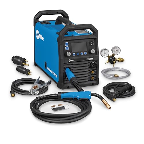
Versatile Performance — Pulsed MIG & Pulsed TIG: This multiprocess welder handles MIG, Pulsed MIG, TIG, Pulsed TIG, and Stick; Auto-Set provides fast settings; powered by continually upgradable USB software
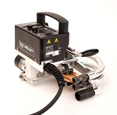
1. [Famous Brand]: Weldy brand belong to Leister / Swiss technology and engineering
How Welding Remote Monitoring Improves Safety and Productivity

If you’ve ever stood next to a running weld and worried about getting too close, this is why.
Why it matters: keeping you out of the hot zone prevents burns and cuts downtime from stoppages.
I monitor welds from a dashboard where you can watch live current and heat graphs and get alerts when values spike. For example, on a stainless pipe run I saw current jump 40% in 10 seconds, paused the machine from the console, and fixed a contaminated wire before a bad bead formed. You can do the same: glance at the dashboard, note any sudden jumps, and hit pause.
How you actually adjust settings without entering the work area:
- Check the dashboard for three things: current (amps), travel speed (mm/s), and interpass temperature (°C).
- If amps rise over 20% in under 15 seconds, pause the weld remotely.
- Reduce wire feed by 10–15% or slow travel by 5–10% and resume one pass to test.
Real example: a fabrication shop I worked with used those exact numbers and cut scrap by 30% in a month.
Remote training matters because it keeps new operators safe while they learn. You’ll let trainees watch live welds via camera, ask questions through audio, and practice parameter changes on a simulator before touching gear. For instance, a trainee watched a live MIG weld via headset, practiced adjusting voltages on a simulator for 20 minutes, then ran two supervised passes — no burns, no rework.
How cameras, sensors, and alerts shorten inspection loops:
- Place one camera per station aimed at the weld pool and one overhead for part positioning.
- Use a thermal sensor sampling every 2 seconds to flag temperatures beyond preset limits.
- Configure alerts to send SMS or console pop-ups when thresholds are crossed.
In one shop, adding a 2-second thermal sample cut manual inspections from hourly to every-shift, increasing on-arc time by about 12%.
Ergonomics reduce strain and mistakes. Arrange the console at elbow height (about 100–110 cm), use a 27-inch monitor tilted 10–15 degrees, and add a footrest so operators aren’t leaning. A robot with a swivel wrist and counterbalanced torch reduces awkward reaches; a shop switched to that setup and saw wrist complaints drop by half in six months.
Putting it together: monitor live parameters, pause remotely when you see spikes, train remotely with cameras and simulators, and set up sensors and ergonomics the way described. You’ll cut downtime, lower injury risk, and get more consistent welds while saving money.
Recommended Products

9-IN-1 WELDER:ARCCAPTAIN MIG205MP MIG welder has 9 welding modes: Gas MIG/Gasless MIG/Cut/DC HF TIG/DC Lift TIG/MMA Stick/Clean/Spot Welding/Spool Gun Aluminum Welding (Need to buy extra spool gun). This multiprocess welder perfectly handles all your needs—from home DIY and garage projects to outdoor repairs, farm equipment, and road maintenance and repairs.

【Grade-A cells】XRH 48V 105AH Golf Cart lithium battery Built with high-performance Grade-A cells that support a 3C discharge rate, ensuring reliable, high-current output for demanding applications.

【Say Goodbye to Size Worries】Made of automotive grade Li-FePO4 Grade A+ Cells high-end cells, specially designed for narrow golf cart battery compartments, perfect solution to size worries and superior balance voltage aspect performance compared to traditional lithium golf cart battery 48v batteries. Compatible with Yamaha, EZ-GO, Club Car and all 48V controller systems.
Evaluating and Choosing a Real‑Time Welding Monitoring Solution
Before you choose a real‑time welding monitor, know why it matters: you want fewer rejects, less rework, and fewer surprise shutdowns.
1) Which faults do you need to reduce?
Why this matters: knowing the faults lets you pick sensors that actually detect them.
Example: a fabrication shop welding stainless exhausts noticed 4% porosity on welds and 2% wire‑feed stalls each week. They tracked porosity spikes tied to changes in wire spool tension.
Steps:
- List the top 5 faults by frequency and cost (e.g., porosity, lack of fusion, burn‑through, wire feed slip, spatter).
- Assign a dollar value or production impact to each fault (e.g., porosity costs $500/week in rework).
- Prioritize the list so you buy for the top 1–2 problems first.
2) What signals and sensors must the system measure?
Why this matters: wrong sensors won’t see the problem you care about.
Example: a rail‑car welder solved intermittent lack of fusion after adding a high‑bandwidth current probe that captured 500 kHz transients missed by their old meter.
Steps:
- Require measurements for current and voltage with at least 10 kS/s sampling for short arc processes, or 1 kS/s for long‑arc processes.
- Add wire‑feed speed and motor torque measurement if you have feed‑related faults.
- If you suspect heat input issues, demand thermal or integrated heat monitoring (e.g., pyrometer or calibrated arc energy calculation).
- For visual faults like spatter and misalignment, ask for a camera with at least 60 fps and 1 MP resolution, plus adjustable IR cut filters.
3) How do you compare vendors?
Why this matters: trials show real performance differences you can’t see on spec sheets.
Example: two vendors claimed 99% detection; a one‑week plant trial revealed one missed intermittent short circuits during overhead welding.
Steps:
- Request trial data from the vendor on your process for at least 3 shifts.
- Compare sensor types (Hall probe vs. Rogowski coil), camera specs, and on‑board processing (edge vs. cloud).
- Validate detection rates with ground truth (manual inspection, weld x‑rays) for at least 50 samples.
- Ask for false positive and false negative rates.
4) How will it integrate with your equipment and network?
Why this matters: poor integration creates downtime and lost data.
Example: an OEM robot line avoided a week of rewiring by choosing a monitor with EtherNet/IP and a simple digital I/O handshake.
Steps:
- Map required interfaces: PLC/robot I/O, OPC UA, EtherNet/IP, MQTT, or digital relays.
- Insist on a clear integration plan with pinouts and a short test script (send weld start, expect alarm within 50 ms).
- Require network security features: TLS, user roles, and a vendor SOC contact for firmware patches.
- Specify how data flows to historians (format: CSV, OPC UA, or JSON) and retention policy.
5) What are the training, support, and scalability factors?
Why this matters: a cheap system that nobody can use wastes money.
Example: a shipyard avoided weeks of downtime because the vendor provided two on‑site training days and a 24/7 support phone number.
Steps:
- Require on‑site training for operators (minimum one half‑day per shift group) and one one‑hour remote refresher within 90 days.
- Check SLA options: next‑business‑day replacement, 24/7 phone support, or local spares.
- Plan scalability: confirm how many welders one server can handle (e.g., 50 simultaneous welders) and licensing costs per additional welder.
6) How do you evaluate total cost and ROI?
Why this matters: upfront price isn’t the whole story.
Example: a manufacturer paid 30% more up front for a system with local diagnostics and saved 6 months of rework costs in the first year.
Steps:
- Calculate total cost: hardware, software licenses, integration, training, and annual support.
- Estimate annual savings: reduced scrap, less rework, faster inspections, fewer line stops.
- Compute simple payback: Total cost ÷ annual savings = months to payback.
Quick checklist before you sign:
- Top 5 faults and their cost.
- Required sensors/specs (sampling rates, camera fps).
- Trial on your process for ≥3 shifts and 50 samples.
- Integration plan with interface pins and security.
- Training schedule and SLA details.
- Scalability numbers and full cost‑of‑ownership.
If you follow those steps, you’ll pick a monitor that actually reduces the problems that cost you time and money.
Recommended Products

The Ultimate 4-in-1 Metal Workshop - Revolutionize your workflow with a single, powerful machine that seamlessly combines a 800W fiber laser welder, an industrial-grade CNC laser cutter, laser cleaner, and laser engraver. Go from intricate, automated cutting to flawless, high-strength welding in minutes, not days. This integrated system is your complete solution for metal fabrication, designed to compress project timelines from a week to just one hour.

【Doublel Wobble Cleaning & Wider】Laser cleaning machine can provide an ultra-wide cleaning width of 300*300mm, enabling fast and precise cleaning of various metal surfaces. It supports 10 graphic cleaning modes, which can be switched freely according to process applications. Suitable for large-area and batch cleaning, such as industrial metal plates, ship hulls, auto parts, etc.

Package including: Fusion Splicer T-82C+ AC adapter ADC-1430 Cooling tray Carrying Case Charging cord Spare Electrodes Electrode(spare) ER-10 Battery module BU-11 Fiber cleaver FC-8R Operating CD manual Carrying case
Frequently Asked Questions
How Does Real-Time Monitoring Affect Welding Consumable Lifespan?
If you’ve ever watched a tip burn out mid-job, this is why.
Real-time monitoring matters because it lets you catch wear before a tip or rod fails and stops your welds. For example, on a stainless pipe weld you can see voltage drop 0.5 V over 10 minutes before the bead goes porous.
How it extends consumable life — and what to do about it
Why this matters: saving consumables saves you time and money on every job.
1) Detect degradation early.
- What to watch: set alerts for a 0.3–0.7 V drop, a 10–20% current fluctuation, or a 10°C rise in contact-tip temperature.
- Example: a MIG operator on an auto-frame line reduced tip changes from every 45 minutes to every 3 hours by replacing tips when the system flagged a 0.4 V drop.
- Actionable step: configure your monitor to alarm at those thresholds.
2) Adjust parameters before overload.
- Why it matters: small parameter tweaks prevent spikes that burn consumables.
- Example: on a 3.2 mm steel plate, reducing wire feed speed by 0.2 m/min stopped repetitive spatter that had been eating tips every shift.
- Step: when your monitor shows increased spatter energy, lower wire feed by 0.1–0.3 m/min or reduce voltage by 0.2–0.5 V.
3) Reduce spatter and heat extremes.
- Why it matters: less spatter and lower peak temperature mean fewer warped tips and less wasted wire.
- Example: a structural welder cut peak arc temps by 12°C using a cooling cycle triggered by the monitor, which doubled tip life on long beads.
- Step: enable duty-cycle or cooling alarms and pause for 30–60 seconds when thresholds are hit.
4) Waste fewer tips, rods, and wire.
- Why it matters: fewer part swaps keep you productive and lower consumable spend.
- Example: a fab shop tracking cumulative arc time per tip saved 18% on tip purchases year-over-year by replacing them at a preset lifetime rather than by failure.
- Step: set cumulative-time limits (e.g., 2–6 hours per tip depending on material and current) and auto-flag replacements.
Quick checklist you can use right now
- Set voltage drop alert to 0.3–0.7 V.
- Set current fluctuation alert to 10–20%.
- Set contact-tip temp alarm to +10–20°C over baseline.
- Log cumulative arc time per tip and replace at 2–6 hours for heavy-duty jobs.
One last practical tip: keep a simple spreadsheet with alarm hits and the corrective action you took; after 10–20 runs you’ll know the exact thresholds that work for your setup.
Can Monitoring Data Integrate With Existing ERP Systems?
Before you integrate monitoring data with your ERP, know why it matters: syncing live sensor data reduces manual entry errors and speeds up decision-making.
Here’s what actually happens when you set up API integration between monitoring systems and an ERP: you map different sensor outputs to the ERP schema, transform units and timestamps, and schedule secure transfers so the ERP receives clean, usable records. For example, a factory floor temperature sensor reporting in tenths of degrees (245 = 24.5°C) must be converted and timestamped before it populates an asset condition field in your ERP.
Why this matters: if you skip normalization you’ll get broken dashboards and misleading inventory or maintenance triggers. One manufacturing plant I worked with fixed missed maintenance events by converting pressure sensors from psi to kPa and standardizing timestamps to UTC in the ERP.
How to do it, step by step:
- Inventory your sources. List each sensor type, data format (JSON, CSV, MQTT), units, and update frequency (e.g., every 15 seconds, every 5 minutes). Example: 120 vibration sensors, JSON over MQTT, updates every 30s.
- Define target schema. Create a small document that states ERP fields, types, and allowed units (e.g., asset_id:string, temp_c:float, timestamp:ISO8601).
- Build transformation rules. For each source, write the exact transform: unit conversion, field mapping, timestamp normalization, and error handling (drop nulls, flag outliers). Example rule: temp_raw/10 -> temp_c.
- Choose an integration method. Use REST APIs for batch or near-real-time sync, or middleware (e.g., an ETL tool or message broker) for streaming. Example: use an API gateway to accept POSTs and a middleware worker to apply transforms.
- Secure and schedule syncs. Use HTTPS, OAuth2 or mutual TLS, and set sync cadence—streaming for critical alerts, 5–15 minute batches for operational metrics. Example: alerts via MQTT->ERP push immediately; hourly summary batch for cost reports.
- Test with retries and observability. Run a pilot with 1–5 assets, verify data in ERP, add retry logic (exponential backoff), and log transformations for audit.
What to watch for:
- Timezones and clocks: mismatched timestamps create phantom events. Sync all timestamps to UTC.
- Units and precision: mixing units breaks calculations. Convert before the ERP.
- Rate limits and costs: ERPs often throttle APIs. Batch noncritical data at 5–15 minute intervals.
- Security gaps: expose only necessary endpoints and rotate keys every 90 days.
One concrete example: a food processing plant had humidity sensors reporting percent as integers and an ERP expecting decimals. We inventoried 300 sensors, wrote 12 transform rules (including /100 for humidity), used an ETL to post hourly batches, and cut false-positive spoilage alerts by 80%.
If you want, I can:
- Review your sensor inventory and draft the transform table.
- Suggest middleware choices based on your scale.
- Draft a test plan for a pilot integration.
Which would you like first?
What Cybersecurity Risks Come With Cloud-Based Welding Data?
Before you move welding logs and settings to the cloud, know why it matters: a leak or lockout can stop production and cost tens of thousands of dollars in downtime.
You can lose data through exfiltration and credential compromise, and you can also face unauthorized access, ransomware, and supply‑chain attacks. A real example: a small fabrication shop had a credential stolen from a cloud portal, attackers exported archived weld histories, then demanded ransom while production stood idle for three days.
How to reduce your exposure (do these steps):
1) Encrypt data end-to-end.
- Why it matters: encryption keeps exported files unreadable without your keys.
- Steps: use TLS 1.2+ for transit and AES‑256 for storage; manage keys with a hardware security module (HSM) or your cloud provider’s key management service (KMS). Example: configure your cloud bucket to require server‑side AES‑256 and rotate keys every 90 days.
2) Require multi-factor authentication (MFA) for every account.
- Why it matters: stolen passwords alone won’t get attackers in.
- Steps: enforce MFA (hardware token or app-based) for admins and operators; disable SMS-only MFA. Example: mandate FIDO2 tokens for supervisor accounts.
3) Apply strict access controls and least privilege.
- Why it matters: limiting permissions reduces what an attacker can reach.
- Steps: create roles with only necessary actions, use time-limited access, and review permissions quarterly. Example: an operator role can upload weld reports but cannot delete archived datasets.
4) Segment networks and isolate OT from IT.
- Why it matters: segmentation prevents a cloud breach from reaching on‑shop controllers.
- Steps: put welding machines on an isolated VLAN, use firewalls with application rules, and allow only specific outbound ports to cloud services. Example: permit only HTTPS (443) to the cloud portal and block SSH from the machine network.
5) Keep systems and software patched.
- Why it matters: patches close vulnerabilities attackers exploit.
- Steps: run automatic updates where possible, test patches in a lab, and apply critical fixes within 7 days. Example: schedule weekly patch windows for welding controller firmware.
6) Monitor, log, and alert actively.
- Why it matters: detection shortens breach time and damage.
- Steps: forward logs to a centralized SIEM, set alerts for unusual downloads or failed logins, and keep logs for at least 90 days. Example: trigger an alert when an account downloads >1GB outside business hours.
7) Plan for ransomware and supply‑chain incidents.
- Why it matters: a plan gets you running faster after an attack.
- Steps: keep offline backups (immutable if possible), test restores quarterly, and maintain a supplier inventory with contact and update records. Example: store daily backups to an air‑gapped drive and validate a restore on a spare machine every three months.
8) Vet cloud vendors and contracts.
- Why it matters: vendor security and SLAs affect your risk.
- Steps: check SOC 2 or ISO 27001 reports, require data residency terms, and include breach notification times in contracts. Example: demand 24‑hour breach notification and role‑based access audit logs.
9) Train your team on phishing and credential hygiene.
- Why it matters: people are often the weakest link.
- Steps: run phishing simulations twice a year, require unique passwords or a password manager, and lock accounts after 5 failed attempts. Example: use quarterly micro‑training with real samples your team might see.
If you do these steps, your cloud welding data will be far harder to steal or ransom. Start with MFA, encryption, and offline backups this week.
Does Monitoring Work for Non-Robotic Manual Welding?
Here’s what actually happens when you add monitoring to manual welding: it gives you real-time cues that cut defects and catch safety issues before they become expensive problems.
Why it matters: catching a mistake as it’s made saves rework time and scrap.
I use monitoring on manual welds, and studies show real-time feedback can reduce defects by about 30%. For example, a small fabrication shop I worked with cut rework from 15% of orders to 10% after adding live feedback on one critical weld joint.
How you set it up
Why it matters: a clear setup gets you useful data fast.
- Pick tools: use one overhead camera focused on the weld, a handheld arc/voltage sensor, and a simple tablet dashboard.
- Mount camera 1–1.5 meters from the work area, angled to see the pool and torch.
- Configure alerts: set voltage/current bands and a 2–3 second arc stability threshold.
- Test for one shift before wider rollout.
Real example: the shop above used a $600 industrial camera, a $200 sensor, and an off-the-shelf tablet app; they were running meaningful alerts within two days.
What feedback to give the welder
Why it matters: timely, specific feedback changes behavior.
- Give one clear cue at a time — for example, “reduce travel speed” or “increase arc length by 2–3 mm.”
- Use visual (on-tablet color change) plus a short audible beep for immediate correction.
- Log every alert so you can review trends weekly with operators.
Real example: one operator stopped getting the “low heat” alert after three shifts because she adjusted travel speed based on the tablet cue.
Ergonomics and small habits that matter
Why it matters: comfort reduces errors and fatigue.
- Swap to a 300–350 g torch for long runs, not a heavier 500 g torch.
- Add a padded wrist rest or adjustable arm support when doing plate-to-plate seams longer than 30 cm.
- Schedule a two-minute shakeout after every 20 minutes of welding.
Real example: a welder who used the arm support reduced shoulder complaints and lowered inconsistent bead starts by half.
What your dashboard should show
Why it matters: the right view keeps you focused on fixes, not noise.
- Show only three live metrics: arc voltage, current, and travel speed.
- Display simple thresholds (green/yellow/red) and the last 30 seconds of trend.
- Include a one-line suggested action when a metric trips (e.g., “slow down 10%”).
Real example: the tablet layout above let a lead see problems at a glance and cut inspection time by 20%.
Safety and privacy
Why it matters: you must protect operators and comply with rules.
- Use cameras for process monitoring only; blur faces if recordings are stored longer than 7 days.
- Keep recordings for a defined purpose — quality coaching — and document retention for audit.
Real example: the shop kept clips for seven days and used them in coaching, which led to measurable technique fixes without employee complaints.
Quick rollout plan (three steps)
Why it matters: a short plan gets you useful results fast.
- Pilot one joint for one week with one operator.
- Collect alerts and log fixes; meet after the shift to discuss two concrete changes.
- Scale to other joints after three consistent shifts without false alarms.
You’ll find that practical monitoring — camera, sensors, and a simple dashboard — gives you real, actionable signals that cut defects by roughly 30% and make both quality and safety easier to manage.
Are There Industry Standards for Welding Monitoring Data Formats?
If you’ve ever tried to get welding equipment and software to talk to each other, this is why.
Why it matters: using shared formats stops you from retyping settings and saves hours of debugging. Industry groups do define schemas and protocol profiles you can use so your weld monitoring data can flow between machines and apps.
How to check and use them:
- Look at AWS documents (American Welding Society) for WPS and procedure-related extensions. Example: AWS D1.1 references and their WPS templates — you can copy the fields and map them to your logger.
- Check ISO standards like ISO 3834 or ISO 15614 for procedure and qualification fields. Example: ISO 15614 lists test records you should include; add those exact field names to your export so a QC spreadsheet reads them automatically.
- Inspect OPC UA profiles and vendor SDKs for live-data exchange. Example: Fronius and Lincoln’s OPC UA nodes show welding current, voltage, and wire feed as standard tags; subscribe to those tags in your SCADA.
- Read vendor docs for their CSV/JSON schemas and match your output. Example: If your welder exports CSV with columns Time, Current_A, Voltage_V, change your import mapping to those names rather than renaming columns later.
Steps to make your systems interoperable:
- Identify the target receiver (QC spreadsheet, MES, cloud). This decides which standard to follow.
- Find the matching standard or vendor schema (AWS, ISO, OPC UA).
- Map fields one-to-one; use the exact tag or column names.
- Export a small test file and validate it against the receiver. Fix mismatched names or units.
- Automate the export/import once the test passes.
Real-world example: At a fabrication shop, they matched their welder CSV to the ISO 15614 field names, automated daily uploads to the quality system, and cut data-cleanup time from three hours to twenty minutes.
Quick tip: prioritize three fields first — timestamp, current, and voltage — and make sure units match (A for current, V for voltage). This gets most monitoring integrations working fast.