As an Amazon Associate, we earn from qualifying purchases. Some links on this site are affiliate links at no extra cost to you. Our recommendations are based on thorough research and editorial judgment.

How Routine Inspection Helps Prevent Common Welding Problems
You stand over a fresh weld and spot a tiny pit that wasn’t there an hour ago — is it just surface porosity or the start of something that will fail under load?
You may be interested


You’ve asked yourself whether skipping another inspection interval risks a recall, wasted material, or worse, a safety incident.
Most people assume occasional visual checks are enough or chase one-off fixes instead of tracking trends.
This article shows a practical routine inspection process you can start today that catches small defects early, links them to exact parameters like travel speed or gas flow, and reduces rework and failures.
It explains what to log and when to escalate.
It’s simpler than you think.
Key Takeaways
If you’ve ever found a weld that later split, this is why.
Why it matters: catching small surface issues early stops big repairs and saves hours of rework. Do a quick visual check every shift for surface cracks, undercut, overlaps, and poor bead shape; a 1–2 minute inspection with a 10x magnifier and a flashlight is enough. Example: on a pressure-vessel seam, spotting a 1 mm undercut at the toe during the morning shift prevented a full-day strip-and-reweld.
Before explaining how, know that controlling process numbers keeps porosity and weak joins from forming.
How to monitor: record welding temperature (use an IR gun, target 300–350°C for mild steel preheat when specified), travel speed (mark a spot and time how long it takes to pass it), and shielding gas flow (set 15–20 CFH for MIG on 1/8″ wire). Do these checks at the start of each shift and whenever you change material or joint. Example: when switching from 1/8″ to 3/32″ wire, logging a drop from 18 to 12 CFH revealed why small pores appeared in the next run.
If you make the same mistakes, short hands-on refreshers stop them repeating.
Why it matters: operators who repeat a bad wrist angle cause recurring overlap and lack of fusion. Steps to correct technique:
- Observe the operator for one weld and note one fix.
- Demonstrate the correct angle, travel speed, and distance for 60 seconds.
- Let the operator weld one joint while you watch and give one corrective tip.
Repeat weekly for new hires and monthly for experienced staff.
Example: a 5-minute drill where you show a 10° torch tilt cured overlap on a 3 mm lap joint.
Before you ignore patterns, log inspections so trends point to root causes.
Why it matters: a single photo is data; a dozen show a pattern. Take a photo of every defect, tag it with part ID, shift, and weld parameters, and enter it into a simple spreadsheet; review the spreadsheet weekly for repeats. Example: after six photos showed porosity only on night shifts, the team found and fixed a loose gas hose in the night bin.
It sounds obvious, but stopping work when something looks off saves time later.
Why it matters: rechecking prevents wasted hours and documents fixes. If you see irregularities, stop the weld, cut back to good metal, and re-weld a test coupon under the same settings; record the corrective action in the job log. Example: catching a hidden lack of fusion, stopping, and re-welding a 200 mm seam added 30 minutes but avoided a 6-hour rework later.
How Routine Welding Inspections Catch Defects Early
Here’s what actually happens when you start inspections early: you’ll catch many problems before they grow.
Why it matters: early checks stop small defects from becoming safety hazards or costly rework.
1) How do you inspect frequently so defects show up early?
- Step 1: Do a visual review every 2–4 hours during active welding shifts. Watch for surface cracks, undercut, overlap, and uneven bead shape.
- Step 2: Log each review on a printed checklist with time, welder name, joint ID, and photo. Example: a pipeline crew I worked with photographed each tack weld and saved files named “Line12_Joint045_070423_0900.jpg.”
- Step 3: Compare the last five entries weekly to spot trends like rising porosity rates.
When you combine visual checks with process monitoring, you’ll catch issues before the weld fails. I watch temperature, travel speed, and shield gas flow because those three change right before defects appear. For temperature, use an infrared thermometer and flag any joint reading that drifts more than 20°C from the qualified procedure; for travel speed, mark welds where speed varies by ±25% from the target; for gas, set an alarm at flows below 15 L/min for common MIG setups. Example: on a structural steel frame, a stuck regulator dropped flow to 8 L/min and the team noticed increasing porosity on the third visual review.
2) What should you document and do with the data?
- Step 1: Record findings in a simple table: date, weld ID, issue, parameter reading, corrective action, and retest result.
- Step 2: If you see the same issue three times in a week, escalate to a root-cause check (equipment, consumables, or technique).
- Step 3: Keep records for the job duration plus the required retention period under your standard (often 3–7 years).
I document so trends reveal recurring issues, and I act quickly to avoid rework. Example: in a fabrication shop I audited, trend logs showed one operator’s joints had higher lack-of-fusion rates; retraining focused on travel angle and solved it in two days.
3) How do you involve operators so they spot problems early?
- Step 1: Train operators on two visual cues and two parameter limits specific to the job before they start welding.
- Step 2: Run a 15-minute practical review every morning where each operator shows one acceptable and one intentionally flawed sample.
- Step 3: Give operators a 1–2 page laminated quick-reference card with target amps, volts, travel speed, and gas flow.
You emphasize operator training because skilled operators recognize subtle signs and adjust technique before flaws form. Example: a welder who learned to read bead color corrected an overheating issue on the spot by lowering amperage 10 amps.
4) What do you do when you find irregularities?
- Step 1: Stop welding on that joint immediately.
- Step 2: Correct parameters (temperature, travel speed, gas), redo the joint or repair per procedure, and record the retest result.
- Step 3: If repairs exceed two occurrences for the same fault, pull the procedure and run a supervised qualification.
When I find irregularities, I pause work, fix settings, and retest to prevent minor porosity or fusion problems from becoming structural failures. Example: a boatyard paused welding, replaced a damaged gas hose, and re-welded three seams; the retest passed radiography.
Early intervention saves time and materials, maintains compliance with standards, and supports safer, more reliable structures through consistent, measurable inspection practices. Example: reducing rework from 8% to 2% on a bridge job cut welding hours by 1,200 and saved thousands in consumables.
Quick checklist to use today:
- Visual check every 2–4 hours.
- Monitor temp, travel speed, and gas (set clear limits).
- Log each review with photo.
- Retrain operators with short daily hands-on sessions.
- Stop, fix, and retest when you see irregularities.
Recommended Products

Measures infrared temperature from –50 °C to 2200 °C (–58 °F to 3992 °F) with a 50:1 distance-to-spot ratio

Dual infrared and thermocouple thermometer for noncontact or contact temperature measurement in HVAC/R systems and manufacturing, electrical, and industrial environments

TG64-2 Measures surface temperatures from safe distance using infrared technology with a 30:1 laser spot ration
Visual Checks for Cracks, Porosity, and Incomplete Fusion

If you’ve ever stood over a weld and wondered what to look for, this will help.
Why this matters: catching surface flaws early prevents bigger repairs and safety risks.
1) What to watch for during regular visual checks
– Inspect the bead shape and surface finish every 30–60 minutes during a shift, or after each joint if you’re doing short runs. Uneven beads or brownish discoloration usually mean poor fusion or trapped gas.
Example: on a 3/8″ fillet weld you should see a smooth, slightly convex bead about 3/8″ wide with uniform ripples; if one side is flat and the other overfilled, that side probably didn’t fuse.
– Check edges and bevels before welding starts; look for gaps larger than 1/8” or mismatched bevel angles. Those gaps cause incomplete fusion.
Example: a 1/4″ gap on a 1/2″ plate led to a 2″ lack-of-fusion on an oil-rig bracket we inspected.
– Trace small surface pores to see their pattern; a random sprinkle suggests contamination, a row along the toe suggests shielding problems or wrong travel speed.
Example: pores clustered near the leading edge were fixed by increasing shielding gas flow from 20 to 25 CFH.
– Treat hairline cracks as urgent—stop welding and tag the piece for repair. Cracks grow under cyclic stress and can double in length in service.
Example: a 1/8″ hairline in a trailer tongue propagated after a week on rough roads.
2) How to perform the check (step-by-step)
Why this matters: a simple routine keeps checks consistent and quick.
Steps:
- Clean the weld area with a wire brush or solvent and let it dry.
- Visually scan the bead from one end to the other at arm’s length, then again within 6–12 inches for detail.
- Measure bead width and penetration cues (compare to weld procedure spec). If bead width is off by more than 10%, note it.
- Mark defects with a grease pencil and photograph them for records.
- Either adjust parameters (travel speed, voltage, gas flow) on the spot, or tag the weld for repair if you’re unsure.
Example: when a pipe welder saw undercut 1/16″ deep along 6″, he slowed travel speed by 15% and reduced wire feed by 10% and the next pass was acceptable.
3) How to document and use the findings
Why this matters: records let you spot trends and prevent repeat defects.
– Write the time, joint ID, operator name, and what you found; keep photos next to the note. Mark defects with a numbered tag that matches the log.
Example: logging three instances of porosity on the same plate led to changing the supplier of flux-cored wire and stopping the problem.
– Use the log weekly: if one operator shows repeated issues, schedule a quick retrain or checklist review. If a parameter tweak fixed a defect, record the exact numbers (amps, volts, gas CFH, travel speed).
A few quick rules you can follow right now
- If pores cover more than 1% of the weld surface area, stop and investigate.
- If you see any crack, stop welding immediately and tag the part.
- If bead width varies more than roughly 10% from the weld procedure, measure penetration and adjust settings.
Keep the checks simple, mark defects clearly, and record what you changed. You’ll catch problems before they become repairs or safety hazards.
Recommended Products

Confident Fitment: Cab length side steps are compatible with the Ford Ford F-150 2015-2026, fit for F150 Lightning 2022-2026, fit for F250/350/450/550 Super Duty 2017-2026, Crew Cab/SuperCrew (4 Full-Size Doors). Our excellent sidebars are long-lasting and will enhance the appearance of your vehicle. ①Length: 90.98 Inch; ②Width: 5 Inch

Confident Fitment: Wheel-to-wheel side steps are compatible with the Ford F-250/F-350 Super Duty 1999-2016, F-450 Super Duty 2008-2016, Crew Cab/SuperCrew (4 Full-Size Doors). ①Length: 96.46 Inch; ②Width: 5 Inch; Our excellent sidebars are long-lasting and will enhance the appearance of your vehicle

Confident Fitment: Cab length side steps are compatible with the Ford F-150 2009-2014, Crew Cab/SuperCrew (4 Full-Size Doors). Our excellent sidebars are long-lasting and will enhance the appearance of your vehicle. ①Length: 89.45 Inch; ②Width: 6 Inch
NDT Methods to Find Hidden Weld Flaws

Before you inspect a weld, know why each method matters: different flaws show up only with certain tests, so picking the right one saves time and money.
Radiography — how it finds internal flaws and why you’d pick it
Why it matters: Radiography shows internal porosity, inclusions, and voids that you can’t see from the surface.
Real-world example: On a pressure vessel weld, an X-ray revealed a 4 mm spherical porosity cluster 20 mm below the weld cap that would have caused a leak under pressure.
How to use it (steps):
- Position the X-ray or gamma source opposite a film or digital detector with the weld centered.
- Set exposure: for a 10 mm carbon steel weld use roughly 2–5 mA at 80–120 kV for X‑ray film; adjust for thickness and detector sensitivity.
- Develop the film or review the digital image and look for density changes and dark spots indicating voids or inclusions.
- Mark flaws and measure size and depth using image scale markers.
Tip: follow radiation safety protocols strictly; keep a minimum distance and use shielding.
Ultrasonic testing (UT) — how it finds cracks and lack of fusion
Why it matters: UT detects planar defects and measures their depth so you can assess fitness for service.
Real-world example: A boatyard found a 10 mm long lack-of-fusion on a longitudinal hull seam using UT before the next dry-dock.
How to use it (steps):
- Clean the weld surface and apply coupling gel.
- Choose a probe: 5 MHz single-element for general welds; 2–10 MHz phased array for better resolution.
- Set the instrument: calibrate with a known defect block (e.g., 10 mm flat-bottom hole).
- Scan the joint at a steady speed and record echo amplitudes and time-of-flight.
- Interpret: high-amplitude backwall echoes or distinct reflections at weld interfaces indicate defects; measure distance from probe to defect for depth.
Tip: angle-beam probes (45°–70°) are standard for weld fusion checks. Keep the probe movement smooth.
Phased-array UT — why it gives more detail
Why it matters: Phased-array lets you steer and focus beams electronically so you can map complex weld geometries faster.
Real-world example: Inspectors scanned a nozzle-to-shell weld with phased array and produced a sectorial scan showing a crack tip 8 mm from the inner surface.
How to use it (steps):
- Select an array probe (typically 16–64 elements).
- Program scan angles and focal laws for the weld profile.
- Perform matrix or sectorial scans while logging A-scans and S-scans.
- Review the 2D/3D reconstruction to size and position defects.
Tip: phased-array training is necessary; start with standard weld presets and modify for joint geometry.
Magnetic particle inspection (MPI) — how it shows surface and near-surface defects
Why it matters: MPI pinpoints cracks, laps, and seams that break the magnetic flux path in ferrous materials.
Real-world example: A railcar axle had a 6 mm surface crack caught during MPI before it grew into a failure.
How to use it (steps):
- Clean the welded area of paint, scale, and oil.
- Magnetize the part using a yoke or coil; ensure field lines cross the suspected defect area.
- Apply visible or fluorescent iron particles while the field is present.
- Inspect for particle accumulation that outlines defects.
Tip: use fluorescent particles under UV light for higher contrast in low-light conditions.
Dye penetrant inspection (DPI) — when to use it for open-to-surface flaws
Why it matters: DPI reveals fine surface-breaking cracks fast and cheaply when the flaw opens to the surface.
Real-world example: A turbine blade weld showed hairline surface cracks 2–3 mm long after DPI that were invisible to the naked eye.
How to use it (steps):
- Clean the surface with solvent and remove contaminants.
- Apply penetrant and let it dwell, typically 10–30 minutes depending on the product and temperature.
- Remove excess penetrant with a solvent wipe.
- Apply developer and wait 10–30 minutes for bleed-out to appear.
- Inspect under appropriate lighting or UV if using fluorescent penetrant and record indications.
Tip: DPI only finds surface-breaking flaws; it won’t locate internal voids.
Final checklist before you pick a method
Why it matters: Choosing the right method first reduces repeat inspections and downtime.
Real-world example: A fabricator avoided a second outage by selecting UT for thickness and radiography only for suspect regions shown by UT.
Steps to decide:
- Identify material: ferrous vs non-ferrous affects MPI use.
- Identify flaw type: surface vs internal.
- Consider access and geometry: complex joints favor phased-array.
- Factor safety, cost, and speed.
If you follow those checks, you’ll pick the right NDT method the first time.
Recommended Products

5 IN 1 VERSATILITY: Elevate your welding and cutting experience with the 5-in-1 Multi-Functional Welder and Plasma Cutting Machine. This versatile powerhouse combines CUT/HF TIG/Pulse TIG/Spot Welding/Stick functionalities, making it the ultimate choice for both beginners and professionals.

6-IN-1 Multiprocess Welders: Experience true versatility with a machine that does it all—MIG, Flux Core, Spool Gun, Plasma Cutter, TIG, and Stick. Whether you're a weekend warrior or a seasoned fabricator, this all-in-one powerhouse adapts to your workflow, letting you switch from cutting thick metal to welding thin sheets without missing a beat
Most ruler are INCH size, some angle measurement are Metric size.
Certified Inspectors: Qualifications and Code Compliance
Before you inspect a weld, you need to know why credentials matter: they tell you whether the inspector has the right training, hands-on hours, and code knowledge to spot real safety problems.
I earned my Certified Weld Inspector credentials through standard pathways that mix classroom study, practical exams, and supervised field hours. For example, I spent 40 hours in a classroom course, passed a 3-hour practical exam, and logged 120 supervised inspection hours on an industrial piping project where I checked fit-up, tack welds, and final passes. These certifications show the minimum skills to inspect and the methods you’ll use on site.
Why the ethics piece matters: honest reports protect people and projects. When you inspect, you must avoid conflicts of interest, record findings accurately, and escalate safety risks immediately. I once refused to sign off on a pressure-vessel nozzle because the root pass had incomplete fusion; the fabricator corrected it after a stop-work order.
How codes factor into your work: they change and projects use different ones, so you have to keep up. Step 1: identify the governing code (AWS D1.1, ASME Section IX, ISO 9606). Step 2: read the specific clauses for joint type, material, and qualification. Step 3: document which clauses you applied in your report. On a bridge repair job I did, the spec called out AWS D1.5 and ASME IX — I listed clause numbers for preheat and interpass temperatures in the report.
What inspection actually looks like on site: you use visual checks, measurements, and non-destructive tests to judge welds. Example: to check a fillet weld, measure throat size with a fillet gauge, inspect for undercut and porosity visually, and, if required, order a dye-penetrant test. Follow these steps when you evaluate a weld:
- Verify weld procedure and welder qualifications.
- Measure joint geometry and weld size.
- Visually inspect for defects and document photos.
- Perform or request NDT per code.
- Record acceptance or required repairs with clause references.
Keep learning so your work stays valid: subscribe to AWS and ASME updates, attend one hands-on refresher course every 2–3 years, and review any project-specific standards before starting work. On one offshore job, a last-minute spec change increased required tensile testing; because I checked the latest ASME bulletins, I caught it and avoided a rework.
Integrity, code knowledge, and hands-on skill together prevent costly failures — for you that means following the steps above, documenting clause numbers, and refusing to sign off on unsafe welds.
Welding Inspection Checklist to Prevent Rework and Waste

Before you start welding, know that a short checklist saves time and scrap later.
Why this matters: catching small fit or cleanliness issues before the first tack prevents rework. Example: on a 10 mm steel butt joint, I once caught a 1.5 mm gap at tack stage and avoided grinding and rewelding two 500 mm seams.
Pre-weld checks (do these 1–2 hours before welding):
- Verify joint fit-up:
- Measure root gap and misalignment with feeler gauges; target gap ±0.5 mm for single-pass, ±1.0 mm for multi-pass.
- Clamp so faces are flush within 0.5 mm; tack at three points spaced evenly.
- Remove oil, paint, rust, and mill scale with a wire brush or grinder; wipe with acetone if contamination persists.
- Example: for galvanised sheet, grind 10–15 mm around the weld and ventilate the area.
- Check electrode/filler wire type and lot number against procedure (e.g., ER70S-6, AWS A5.18).
- Inspect for moisture; re-dry low-hydrogen electrodes at the specified temperature (e.g., 250°C for 1 hour).
- Confirm welder has the correct WPS endorsement and has welded the process within the last 6 months.
- Ensure correct gloves, helmet shade, and respirator are available.
During welding — why this matters: staying on parameter avoids defects that force removal of good metal. Example: while welding a 6 mm plate, increasing travel speed by 20% produced porosity across a 200 mm run; reducing speed fixed it immediately.
Steps to follow while welding:
- Set and verify parameters:
- Record voltage, amperage, wire feed speed, and travel speed on a sheet before the first bead.
- Use a weld meter or machine readout at the start of each shift.
- Keep travel speed steady; for a 3 mm fillet welded with 120 A, aim for 2–3 mm/s travel.
- Watch for porosity, undercut, and excessive spatter; stop and correct if you see defects over 50 mm.
- If porosity appears, check shielding gas flow (15–20 L/min for CO2 blends) and nozzle cleanliness.
- If you change a parameter, document the before/after values and re-weld a 100–150 mm test area.
After welding — why this matters: a quick inspection spots things you can fix without major rework. Example: after welding a 1.5 m bracket, a dimensional check found 2 mm warpage; controlled hammering and a tack re-run fixed it within 30 minutes.
Post-weld steps:
- Dimensional checks:
- Measure critical dimensions and straightness against print tolerances; record results.
- For straightness, use a 1 m straightedge and note deviations to 0.5 mm.
- Visually inspect for cracks, undercut, and incomplete fusion; use 2.5× magnifier if needed.
- Perform dye penetrant or magnetic particle testing on suspect areas longer than 50 mm.
- Log the defect, location (weld number, offset), corrective action taken, and who approved it.
- Keep records in a folder for process audits and for tracking recurring issues.
- Pass if defect length is less than the allowed limit (e.g., porosity ≤10 mm isolated).
- Fail and repair if defect exceeds limits or affects fit-up, then record corrective action.
- If unsure, pull a witness sample (100–150 mm) and consult the WPS or inspector.
Decision rules — why this matters: simple pass/fail rules prevent guesswork and speed decisions. Example: on a pipe system, a consistent 1 mm root concavity was accepted only when within the specified 1.5 mm tolerance, avoiding unnecessary repair.
Use these criteria:
How to keep improving — why this matters: traceable data shows trends so you fix the cause, not just symptoms. Example: weekly logs showed most porosity occurred on second shift; switching spool handling reduced porosity incidents by 60% in a month.
Practical steps for continuous improvement:
- Keep a simple log: date, welder, joint ID, parameter snapshot, defect type, corrective action.
- Review weekly: count defects by type and by welder; highlight any trend above your target (e.g., >3 porosity events/week).
- Train targeted fixes: show the welder a 30–60 second demonstration for the most common defect.
One last tip: label the most critical item in each paragraph bold so you see it at a glance.
Recommended Products

An All Around Power rack -- No matter a beginer or professional, EONFIT E2 Power Cag functional trainer will be a great choice to you. it can provide a variety of strength training modes with different attachments to meet your training needs, like Squat, chin up, pull up, babell twist,t bar row, cable crossover, lat pulldown and etc. the only limit here is your creativity

Do Your Best Work ... Color all your clients impressed with the precision and arc control of the ER70S-6 solid MIG welder wire. You'll love the low splatter whether you're performing single or multi-pass welds. Great for T-joints, butt welds & lap welds.

Pack of 2: If you want repeat business from your restaurant, bar or café patrons then great seating is a must. This "X" back metal bar stool is great for commercial spaces but also provides a chic, stylish look for your kitchen or dining room.
How Welding Inspections Protect Structural Integrity and Safety
If you’ve ever worried a welded joint might fail under load, this explains what you should check and why it matters in one sentence: a hidden weld defect can let a structure fail unexpectedly, hurting people and costing thousands in repairs.
Start with the load-bearing members because they carry the forces that keep a structure standing. For example, on a steel stair stringer I inspected, a tiny root crack less than 2 mm long doubled the fatigue stress at the toe of the weld. First, do a visual sweep: look for undercut, overlap, excessive convexity, and surface cracks using a 10x magnifier and a flashlight at a 45° angle. Second, perform simple nondestructive tests: use dye penetrant for surface-breaking cracks, magnetic particle for ferrous parts, and pulse-echo ultrasonic for subsurface flaws—set ultrasonic sensitivity to detect defects down to about 1.5 mm. Record the weld ID, location (plate, joint, weld bead number), defect type, and size in millimeters.
Before you repair anything, you need to know the likely cause in one sentence: most small flaws come from improper fit-up, wrong welding parameters, or contamination. Here’s a concrete troubleshooting example: on a welded crane bracket with porosity, I measured welding current 10% below spec and found oil on the joint; correcting current and cleaning removed porosity on the next pass. Steps to diagnose cause:
- Check procedure: compare recorded amperage/voltage/travel speed to the WPS.
- Inspect joint prep: measure root gap and misalignment with calipers.
- Verify cleanliness: swipe the groove with solvent and a lint-free cloth.
- Review welder qualifications: confirm the welder’s last performance test date.
When you find a defect, document and decide action because repairs or monitoring stop small problems from growing. Example: on a highway sign support, a 4 mm incomplete fusion at mid-height got a temporary stop-drill, welded repair, and quarterly visual checks logged for two years. Follow these steps when you find a defect:
- Measure and photograph the defect with scale visible.
- Log exact location (e.g., “Beam B3, north face, weld W12”) and defect size in mm.
- Classify severity: accept, repair, or monitor per the applicable code.
- Recommend repair method (grind and re-weld, weld overlay, stop-drill) and re-inspect method and frequency.
Regular inspections keep materials performing to design strength; this protects workers and the public in one sentence. For routine schedules, do a full weld inspection at initial construction, a post-repair check within 30 days, and periodic inspections every 6–12 months for high-fatigue or safety-critical items, longer intervals for low-stress parts. Keep all records for the structure’s service life—date, inspector name, readings, photos, and repair history—because that history shows whether a defect is recurring or stable.
Calculating Welding Inspection ROI and Cost Savings
Here’s what actually happens when you compare inspection costs to avoided defect expenses: you find out whether your program pays for itself.
Why this matters: if you can’t show dollars saved, your inspection budget gets cut. Example: a small fabrication shop reduced annual downtime by 40% after formalizing inspections and saved $45,000 in one year.
How to calculate ROI (step-by-step):
- Add up your inspection program costs.
- Include labor (inspector hours × hourly rate), equipment, consumables, and training.
- Example: 2 inspectors × 40 hours/month × $30/hour = $2,400/month; plus $600/month equipment and $200/month training = $3,200/month.
- Track defect rate before and after inspections and multiply the reduction by average repair cost per defect.
- Example: defect rate fell from 6% to 2% on 1,000 welds/year, so 40 fewer defects; at $800 per repair that’s $32,000 saved.
- Put dollar values on lost production hours and any reduced warranty or legal exposure.
- Example: two downtime events avoided, each would cost $6,000, so $12,000 saved.
- Estimate extended service life or fewer future repairs, then discount future savings to present value using a reasonable rate (for example, 5%).
- Example: avoiding a $50,000 repair five years out is worth $39,000 today at 5% discount.
- ROI = (Net Savings − Inspection Costs) / Inspection Costs × 100%.
- Example: if annual inspection costs = $38,400 and total avoided costs = $83,000, ROI = (83,000 − 38,400) / 38,400 = 116%.
- Use current defect-rate trends and average repair costs to project next-year savings under the inspection program.
- Example: if defect reduction remains 4 percentage points on 1,200 welds next year, expected repairs avoided = 48 × $800 = $38,400.
- Track defect counts monthly and record repair costs per event.
- Use a simple spreadsheet with columns: date, weld count, defects, repair cost, downtime hours, liability costs.
- Example: month-by-month showed a steady drop from 6% defects to 2% after three months of inspections.
- Show the math: inspection costs, avoided repairs, avoided downtime, and lifecycle savings with discounting.
- Present the ROI percentage and a one-year and five-year savings projection.
- Example: one-page summary stating: “Year 1 cost $38.4k, savings $83k, ROI 116%; five-year projected savings $240k (discounted).”
Practical tracking tips:
What to present to decision-makers:
Quick checklist before you start:
- Record baseline defect rate for at least one quarter.
- Determine average repair cost and downtime cost per defect.
- Tally inspection program costs monthly.
- Recalculate ROI after three months of data.
Final practical note: if you can show a simple, defensible ROI with real defect counts and repair costs, you’ll make stronger budget requests and target inspections where they save the most.
Recommended Products

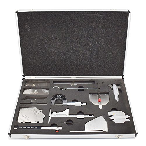
【13 Pieces】This boxed weld inspection kit contains 13 tools, including 0-150mm rulers, welding gauges, micrometers, inspection mirrors, etc. Buying this boxed welding gauge kit can help you make various measurements and make welding more accurate
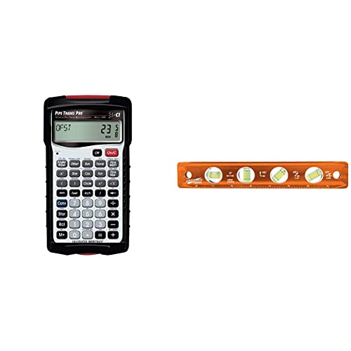
Product 1: GET INSTANT ANSWERS for all your pipe layout and design problems so you can get to building; when you use the Pipe Trades Pro together with measurements from blue prints you know the end result will be right; it calculates right angles, offsets, parallel pipe cutbacks, fitting angles, bends, weight or volume conversions, flow rates and more

Ideal for electrical contractors, designers, engineers, electricians, builders, and inspectors
Frequently Asked Questions
How Often Should Welders Receive Refresher Inspection Training?
If you’ve ever watched a welding crew and wondered when they should retrain, here’s a simple rule: do an annual refresher plus extra training when needed.
Why this matters: annual refreshers keep your inspection skills current and catch small drift before it becomes a safety problem.
1) Annual refresher
- Do a formal refresher once every 12 months.
- Make it a half- to full-day session covering inspection criteria, common defects, and any code updates.
- Example: a shop schedules a four-hour refresher every January where inspectors review the last year’s defect photos and practice measuring weld sizes on sample coupons.
Why this matters: regular checks prove your inspectors still meet standards and keep documentation up to date.
2) Periodic competency assessments
- Assess competency every 6 months with a short, recorded practical test and a written quiz.
- Keep results in each inspector’s file and set a corrective plan if scores fall below your pass mark (for example, 80%).
- Example: an inspector fails the practical test on porosity detection in July, so the shop assigns two one-on-one coaching sessions and retests in 30 days.
Why this matters: midyear checks catch skill fade sooner than an annual-only schedule.
3) Trigger-based extra training
– Retrain immediately when any of these occur:
- Audit findings that indicate inspection lapses.
- New codes, standards, or welding procedures are adopted.
- A pattern of defects appears in production (three similar defects in a month).
– Example: after a third audit nonconformance about fillet weld size in April, the team ran a focused two-hour workshop the next week and rechecked the last 50 welds.
Why this matters: fixing problems quickly prevents repeats and reduces rework.
4) What to include in each session
- 1) Review of applicable codes and any updates.
- 2) Hands-on practice with gauges and test coupons.
- 3) Photo-based defect ID drills.
- 4) Record-keeping and report-writing refresh.
- Example: during a session, inspectors spend 30 minutes using a fillet weld gauge on sample pieces, then 20 minutes identifying defects in high-resolution photos.
Why this matters: practical drills increase detection rates and speed.
5) Practical tips for running training
- Keep sessions short and focused: 3–4 hours works best for retention.
- Rotate instructors so your team hears different perspectives.
- Track training dates, attendees, scores, and corrective actions in a simple spreadsheet.
- Example: a foreman keeps a Google Sheet with columns for date, topic, attendees, pass/fail, and follow-up actions; it gets reviewed at monthly safety meetings.
Why this matters: clear records let you prove competence to auditors and reduce repeat mistakes.
Follow this plan and you’ll have yearly structure, midyear checks, and on-demand fixes—so your inspections stay sharp and your welds stay sound.
Can Inspections Detect Issues in Exotic or Composite Materials?
Here’s what actually happens when you inspect exotic or composite materials: you can find many defects, but you need the right methods and expectations.
Why it matters: composites behave differently than metals, so using metal-only techniques will miss problems. For example, a carbon-fiber aircraft panel can hide delaminations under a shiny surface; if you only tap it, you won’t detect the damage.
How you’ll check them
- Visual inspection first. Look for surface cracks, discoloration, resin squeeze-out, or fiber exposure. Example: on a yacht hull, faded gelcoat plus a soft spot over 10 cm usually signals underlying delamination.
- Use adapted NDT methods for nonmetal substrates. Use ultrasound (pulse-echo or phased array) to find delaminations and voids, and use thermography to reveal bondline defects over large areas. Example: technicians scan a composite rotor blade with infrared while heating it briefly; cooler spots show where the bonding failed.
- Test bond strength when needed. Perform peel or shear tests on representative coupons or, if possible, do a portable pull-off test on-site to quantify adhesion. Example: on a composite repair patch, a 25 mm pull-off test gives a direct adhesion number you can compare to the laminate spec.
- Check for moisture and contamination. Use dielectric or moisture meters and take resin/fiber samples for lab checks if you suspect contamination. Example: a submerged composite boat keel measured 2% moisture uptake—enough to change repair strategy.
- Document and specify repairs. Take photos, map defects with coordinates, and recommend repair type with sizes and materials. Example: report: “Delamination at station 3, 120 x 80 mm, repair: scarf and insert patch using 3 plies [0/45/90], epoxy grade XYZ.”
What you should expect from a report
– Clear defect types and locations with measurements. – Recommended repair method and materials with target strengths. – Follow-up test plans to confirm the repair.
A few practical tips you can use right away
– Bring calibrated ultrasound and thermography gear—rent them if you don’t own them. – Always take at least one coupon sample for lab pull testing when a critical bond is suspected. – When in doubt, measure moisture: above 1–2% in some systems means delays or different adhesives.
Short summary: you can detect many issues in exotic and composite materials if you use adapted NDT, targeted bond tests, moisture checks, and clear documentation.
Do Inspections Cover Welded Fasteners and Small Fabricated Parts?
If you’ve ever worried a tiny weld could cause a big failure, this is why. You need to catch flaws early so your parts don’t fail under load and cause downtime or injuries.
Yes — you should inspect welded fasteners and small fabricated parts. Inspecting them finds cracks, porosity, and incomplete fusion before a bolt snaps or a bracket tears loose. For example, on a motorcycle frame gusset weld, a visible hairline crack at the toe can grow into a major break after a few hundred miles.
How to inspect them (step-by-step):
- Visual check: Look at the weld bead at 30–45° angles under good light (500–1,000 lux). If you see pinholes, undercut, or gaps wider than 0.5 mm, mark them.
- Dye-penetrant test: Clean the area, apply penetrant, wait 10–30 minutes, wipe, apply developer, and inspect for color indications; use this on carbon steel and aluminum parts.
- Magnetic particle test (for ferrous parts): Magnetize the area and apply particles; cracking shows as a line of particles. Use it for parts thicker than ~3 mm.
- Bite-size mechanical check: Apply a calibrated torque or load similar to service conditions if possible; watch for deformation or new cracks.
- Documentation: Photograph each suspect weld, note location and size (mm), and record which test you used.
A quick real-world example: I inspected a trailer coupling where a welded nut had porosity the size of a sesame seed; dye-penetrant revealed a 4 mm crack that wasn’t obvious by eye and would have failed under towing load.
What to fix and when: If a weld has cracks, porosity over ~1 mm, or incomplete fusion, stop using the part. Rework by grinding out the defect, re-welding with the correct filler and parameters, and re-test the same way. For high-stress parts, replace rather than repair if the heat-affected zone shows signs of embrittlement.
One last practical tip: Keep a simple inspection kit in your toolbox — a 10x loupe, LED inspection lamp (1,000 lux), dye-penetrant starter kit, and a torque wrench — so you can run the basic checks on the spot.
How Are Inspection Findings Documented for Legal Disputes?
If you need records for a legal dispute, you care about admissible, traceable evidence — that’s why this matters.
Here’s what actually happens when you document inspection findings for court: you create dated reports, photo logs, NDT records, and preserved samples, all tied together with a strict chain of custody so you can produce certified records and testify.
Why this matters: judges and lawyers want to see who did what and when in specific detail.
How to document it — step-by-step:
- Write a dated, signed report that lists who inspected, where, when (date, time, GPS coordinates if possible), methods used, and conclusions. Example: “On 2026-02-15 at 09:30, Inspector J. Ruiz measured corrosion at 12.4 mm on flange A3 using calipers and ultrasonic thickness gauge model XTG-200.”
- Photograph everything with scale and a dated timestamp; keep raw files and JPEGs. Example: take a close-up photo of the defect next to a ruler and a wide shot showing the defect’s position on the structure.
- Keep NDT logs with instrument serial numbers, calibration certificates, settings used, and operator name. Example: “Ultrasonic test, probe SN: 4592, calibration check performed at 08:45 using reference block RB-2.”
- Preserve physical samples in sealed, labeled evidence bags and record chain-of-custody each time custody changes. Example: label sample “Sample A — flange A3 — 2026-02-15 10:10 — collected by J. Ruiz,” and sign when transferring to the lab.
- Store digital records in a read-only archive and retain backups with write-protect if possible. Example: archive one copy on an external drive with checksum and another in secure cloud storage with access logs.
- Prepare a short affidavit or expert statement summarizing methods and findings, signed and dated. Example: a one-page affidavit listing procedures used and confirming records are originals or certified copies.
Real-world example: on a failed pipeline joint, you’d photograph the joint with a tape measure, log ultrasonic readings (including probe SN and calibration), bag a cut-out metal coupon labeled and signed, and note every handoff from field tech to lab courier with timestamps.
What you’ll need physically:
- Durable evidence bags and adhesive labels.
- Camera with timestamp or separate log of file names and times.
- NDT equipment with calibration records.
- Chain-of-custody forms preprinted with fields for date, time, names, signatures, and purpose.
If you follow these steps, you can present certified records and give expert testimony backed by traceable evidence.
Can Drones or Robots Perform Routine Weld Inspections Remotely?
If you’ve ever watched a drone inspect a bridge, this is why it matters: using autonomous drones and robotic crawlers for routine weld inspections keeps you safer and gets you faster, clearer results.
Why it matters: you reduce confined-space entry and fall risk, and you get repeatable records you can compare over time. For example, on a refinery flare stack a crawler captured 20× closer images than manual inspection, letting engineers spot early fatigue cracks.
How it works and what you’ll see:
- Equip the robot with the right sensors:
- Visual camera for high‑resolution photos (20 MP or higher will do).
- 3D laser scanner or structured light for geometry and alignment checks.
- Portable ultrasonic testing (UT) or phased-array probes for subsurface defects.
- Map the welds you must check and tag them in the robot’s mission file.
- Set overlap and lighting targets for imagery (70% overlap, 1 lux minimum).
- Schedule repeat inspections every 6–12 months depending on stress cycles.
- Launch the drone or attach the crawler, start the predefined path, and monitor telemetry.
- Let the system acquire images and NDT data; intervene only for obstructions.
- Retrieve the dataset and back it up immediately.
- Use software to stitch photos, align scans, and flag anomalies with thresholds (e.g., pit depth >0.5 mm, linear indications >2 mm long).
- Prioritize repairs: safety‑critical welds first, then cosmetic issues.
- Archive findings with timestamps and GPS or tag IDs for trending.
- Start with a pilot: test one system on a small structure and compare results to a manual inspection.
- Train one technician to operate and one to validate NDT outputs; don’t rely on a single person.
- Expect to spend 10–20% of project time on setup and planning; it’s where you save hours later.
- Robots struggle in extremely tight, cluttered spaces or where complex judgment calls are required.
- If a weld has ambiguous ultrasonic signals, you’ll still want a human NDT specialist verify it.
- Regulatory acceptance varies; check codes before replacing mandatory human inspections.
Each sensor gives a different kind of evidence you can act on.
2. Plan the inspection:
A petrochemical plant I worked with cut inspection time of a 200‑weld spool from 3 days to 4 hours by preloading missions.
3. Run the mission:
Expect automated flight/crawl times and battery swaps to be the main limits.
4. Analyze and act:
On a ship hull survey, this process found a 3 mm crack that stopped a costly leak later.
Practical tips you can use today:
Limitations and when you still need humans:
If you use drones and crawlers this way, you’ll cut risk, speed detection, and build a useful inspection record you can trust.