As an Amazon Associate, we earn from qualifying purchases. Some links on this site are affiliate links at no extra cost to you. Our recommendations are based on thorough research and editorial judgment.

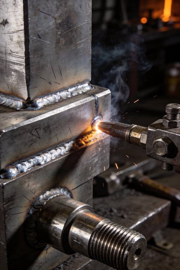
How Better Prep Work Leads to Cleaner, More Repeatable Welds
You set up a weld, pull the trigger, and the bead looks porous or won’t fuse to the parent metal despite following the print. You ask why you keep getting lack-of-fusion and porosity when you thought your procedure was correct.
You may be interested


Most welders blame consumables or technique without checking prep and joint geometry first. This piece shows exactly which prep steps to fix—cleaning to bare metal, creating precise bevels and gaps, keeping material dry and inspected, and matching voltage, wire feed, and travel speed to measured thickness—so you cut defects and make results repeatable across shifts.
It also explains simple log checks and tack practices to prevent distortion and inclusions. It’s easier than it seems.
Key Takeaways
If you’ve ever seen a weld fail after a week, this is why. Clean, degreased surfaces stop oils and dirt from creating porosity and lack of fusion, so your welds come out consistent; for steel, wipe with acetone or a commercial degreaser and use a lint-free rag, then check visually for shine or residue.
Before you start welding, you need to know your joint geometry. Precise bevels, gap, and land measurements give predictable penetration and let you use the same settings part to part; for example, set a 30° single-bevel with a 3 mm root gap and 1 mm land, then record the travel speed and amps you used.
Think of moisture like a hidden enemy. Proper moisture control and baking reduce hydrogen-induced cracking and variability in soundness, so dry parts at 160–200°C for 1–2 hours for high-hydrogen steels and store them in a sealed, dry cabinet at <10% relative humidity.
The fastest way to keep distortion down isn’t brute clamping. Consistent tack spacing and alignment minimize movement, enabling uniform joint geometry for repeatable weld profiles; place 25–30 mm tacks every 75–100 mm and check alignment with a straightedge before final welding.
If you’ve ever lost traceability and then wasted hours guessing parameters, this is why. Controlled storage, inspection, and documentation (thickness, certs, bake/tag) let you pick reliable parameters and reproduce results; put a tag on each stack with material thickness, mill cert number, and bake time so you can reference it when you set amps and wire feed.
Weld Prep : Clean and Degrease to Cut LOF
Before you start cutting, you need a clean, degreased joint so your welds stay repeatable.
Why this matters: contaminants like oil, grease, paint, and mill scale cause unstable arcs and lack of fusion (LOF), which leads to rejects. Example: on a painted 6 mm steel plate, I once got LOF across a 150 mm run because a thin oil film prevented proper fusion.
How to prepare the joint (steps):
- Visually inspect the area for paint, oil, rust, or coatings.
- Remove gross contaminants with a rag and a solvent such as acetone or methyl ethyl ketone (MEK); use enough solvent to wet the surface but don’t soak the core.
- Mechanically remove scale or heavy rust with a 60–80 grit flap disc or a wire brush driven by an angle grinder, keeping the disc flat to avoid gouging.
- For light residues, wipe with clean acetone on lint-free cloths until the cloth shows no discoloration.
- If oxidation persists on stainless or aluminum, passivate or use a stainless-specific pickling paste, following the manufacturer’s dwell time.
- For small, precise parts, consider ultrasonic cleaning in a solvent tank for 5–10 minutes.
- After cleaning, perform a water-break test: wet the surface with water; if it beads, repeat cleaning until it sheets evenly.
- For plates thicker than 12 mm, consider a light preheat of 50–100°C after degreasing to lower hydrogen cracking risk.
Practical tips you’ll use on the shop floor:
- Use disposable lint-free wipes so you don’t reintroduce contaminants.
- Label cleaned joints with a piece of blue tape and the time cleaned if you won’t weld within 30 minutes.
- If you’re welding galvanized steel, remove the zinc around the joint for 15–20 mm to avoid toxic fumes and poor fusion.
Example: I prepped a 10 mm mild-steel flange by grinding a 10 mm V-groove, wiping with acetone until the towels stayed white, then preheating to 80°C for two minutes; the bead stayed even and penetration was consistent.
Inspecting the result: visually check for uniform metal color and run the water-break test; for critical welds, use a dye-penetrant or simple surface conductivity check to confirm no insulating residues remain.
Recommended Products

High-purity 100 percent acetone technical grade. Ideal for industrial solvent applications requiring 100% pure acetone performance.

[High-Efficiency Formula] Designed for thorough cleaning, this wax and grease remover is fast-acting and effective on metal, plastic, and fiberglass, setting the stage for perfect paint jobs.
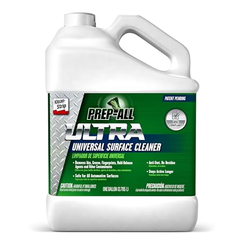
[Advanced Cleaning Technology] Introducing PREP-ALL ULTRA with an innovative emulsion formula combining solvent power in a low VOC, suitable for multiple surfaces.
Edge Prep: Bevels, Gap, and Land for Full Penetration

If you’ve ever stared at two beveled plates and wondered why the weld didn’t go all the way through, this is why.
Why this matters: full penetration gives you the strength and fatigue life your joint needs. Example: a 6 mm thick carbon-steel butt joint that lacks root fusion will fail a bend test even if the cap looks fine.
Bevel angle — what to set and why
Why this matters: the bevel angle controls how the arc and filler access the root. Example: when you’re welding a 6 mm single-V butt, a 30° bevel per side (60° included) is common for SMAW or GMAW with one-sided access; it gives you room for the arc and for enough filler metal.
1) Set the angle: measure with a bevel protractor or a 60° gauge.
2) Aim for ±2° consistency across the joint.
3) If you’re welding thicker material (12–16 mm) increase to 35–45° per side to allow proper penetration and filler placement.
Bevel inspection: check three spots along the joint (start, middle, end) and record angles. If one spot is off by more than 2°, grind it to match.
Gap — how wide and why
Why this matters: the root gap controls arc access and prevents burn-through or poor fusion. Example: on that same 6 mm butt joint, a 1.5–2.0 mm root gap works well with 1.6 mm wire and standard settings; it prevents the arc from bogging or blowing through.
Steps for gap control:
1) Set a target: 0.5× thickness for thin sheet (so for 3 mm use ~1.5 mm), 1.5–2.5 mm for 6 mm plate.
2) Use feeler gauges or a 1.5 mm welding spacer to hold the gap while tacking.
3) Tack at 150–200 mm intervals to keep the gap opening even.
If the gap is too large, you’ll risk burn-through and excessive convexity; if too small, you’ll trap slag or get lack of root fusion.
Land (root face) — size and purpose
Why this matters: the land gives a predictable root thickness and prevents root collapse when you’re welding from one side. Example: for 6 mm plate with single-V prep, leaving a 0.5–1.0 mm land gives you a solid place for the arc to form and stops the root from burning out.
Guidelines:
1) Set the land to 10–20% of material thickness (so 0.6–1.2 mm for 6 mm).
2) Keep the land flat and uniform; grind it parallel to the plate face.
3) If you need deeper penetration for fatigue-critical parts, bevel to zero land only with backing or double-sided welding.
Inspection and documentation
Why this matters: repeatable prep gets repeatable welds. Example: on a production run of five identical brackets, recording bevel angle, gap, and land let the welder reproduce the joint and pass the radiographic exam every time.
How to inspect:
1) Measure bevel at three points with a bevel protractor.
2) Measure gap with feeler gauges at three points.
3) Measure land thickness with calipers at three points.
Document all values and include your tack spacing and filler size.
Quick practical checklist before welding
Why this matters: a short checklist prevents excuses and mistakes. Example: before tacking a repair on a trailer tongue, running this checklist avoided a costly rework.
Checklist:
1) Bevel angles within ±2°.
2) Gap matches spec (use spacer).
3) Land equals target thickness.
4) Tack spacing set and documented.
You can use these numbers and the simple measuring steps to make your preps consistent, so the arc penetrates where you want it and your welds hold up.
Recommended Products

Press brake kit comes unassembled, you do the final assembly and welding.

FIVE TOOLS IN ONE: The tool works as a digital angle finder, inclinometer, miter calculator, protractor and level.
![ARCCAPTAIN Plasma Cutter, [Large LED Display] 50Amps Cutter Machine with 110/220V Dual Voltage DC Inverter IGBT 1/2 Inch Clean Cut Post Flow and 2T/4T, for Beginners DIY](https://m.media-amazon.com/images/I/418eA5bRMGL._SL500_.jpg)
【Powerful Cutting Ability】Switch effortlessly between 110V and 220V for home or workshop use. Achieve professional 1/2" clean cuts on steel, aluminum, and copper with advanced LGBT technology. Perfect for DIY projects and heavy-duty tasks. Recommended maximum cutting thickness: 12mm @ 35A / 110V / 55 PSl; 18mm @ 50A / 220V / 75 PSI. Note: Requires compressed air (compressor sold separately).
Align and Fit-Up Joints to Prevent Spatter Inclusion

If you’ve ever had welds reject because of little dark spots, this is why.
Why it matters: spatter that gets trapped in the joint becomes a hidden defect that causes cracks and porosity later.
1) How do you get the faces to sit flush?
- Step 1: clean the mating surfaces with a wire brush and solvent so you can see contact clearly.
- Step 2: clamp the parts with a face-to-face pressure of about 200–400 lbf (use two C-clamps or a magnetic clamp for flat plate) so the joint faces contact evenly.
- Step 3: use a 0.005–0.010 in feeler gauge to check for gaps every 50 mm along the seam; if the gauge slips, re-shim or tighten the clamp.
Example: for a 150 mm stainless exhaust flange I use two 6 in C-clamps at 50 mm from each end, check gaps at 25 mm intervals, and tighten until a 0.005 in gauge just stops.
Why it matters: holding parts rigid stops movement during tacking so your tack welds stay where you put them.
2) How should you fixture and tack for repeatable fusion?
- Step 1: design or position fixtures so the parts are supported at the neutral axis; use sacrificial stops to prevent rotation.
- Step 2: place tacks at regular intervals: for 3 mm sheet use tacks every 75–100 mm; for 10 mm plate use tacks every 150–200 mm.
- Step 3: after tacking, let the assembly cool to ambient or a consistent temperature (measure with an IR thermometer) and then re-check alignment before running full beads.
Example: when doing a mild-steel bracket, I water-cooled clamp the back edge, put 4 mm tacks at 100 mm spacing, then wait 2–3 minutes and re-clamp before the final weld.
Why it matters: a visible, repeatable alignment reference stops you chasing arc wander and reduces rework.
3) When should you use laser alignment and how?
- Step 1: only use a crossline laser for runs longer than 300 mm or when straightness tolerance is under 0.5 mm per 300 mm.
- Step 2: mount the laser on a low-profile magnetic base centered on one part and rotate the beam to bisect the joint; adjust clamps until the seam follows the line within 0.5 mm.
- Step 3: tack at the ends, re‑verify the laser line, then tack the middle before completing the weld.
Example: on a 1 m long thin-walled tube I set the laser, adjusted supports until the seam tracked the line, tacked at 0, 500, and 1000 mm, then finished the weld.
Practical quick checklist before you weld:
- Clean faces and remove paint/scale.
- Clamp with even pressure (200–400 lbf for flat parts).
- Check gaps every 50 mm with 0.005–0.010 in feeler gauges.
- Tack at specified intervals (75–100 mm for thin sheet; 150–200 mm for plate).
- Let cool and re-clamp; verify alignment (laser if tolerance <0.5 mm/300 mm).
Do it every time.
If you follow those steps, spatter won’t have room to lodge and your welds will behave predictably.
Recommended Products

WIDE APPLICATION:This pipe welder is designed for welding various thermoplastic pipes, including HDPE,PE,PPR,PB, and PVDF materials.It handles pipe diameters from 3.54 to 9.84 inches (90-250 mm) with alignment tolerances ≤0.3 mm,ensuring strong and reliable welded joints.

LONG SERVICE LIFE: High quality lead-free brass, resists corrosion, rust, mineral buildup and high temperature(32℉-200℉)

Frames are made from high-strength ductile iron castings
Material Handling: Store, Inspect, and Control Thickness/Moisture
Before you store materials, you need to know why it matters: keeping them dry and the right thickness prevents weld failures by keeping heat flow and fusion predictable.
1) How should you store plates to prevent moisture and deformation?
Why it matters: wet or warped plates change fit-up and cause hydrogen cracks.
Steps:
- Put plates on pallets or racks at least 6 inches off the ground and cover them with a tarp or plastic sheeting that allows some ventilation.
- Keep stacks no taller than 4 plates for heavy steel to avoid sagging; use spacers between plates every 24 inches.
- Rotate inventory using a simple FIFO tag system: write the arrival date on each plate with a permanent marker.
Example: I once had a 3/8″ plate sag in a yard stack after three months; after switching to 6-inch pallets and 24-inch spacers we stopped seeing warp on similar plates.
Inspect for rust, coating breakdown, and thickness variation before cutting because small differences change heat flow and fusion.
2) What exactly should you inspect before cutting?
Why it matters: unseen rust or reduced thickness will alter weld penetration and cause rework.
Steps:
- Visually scan for rust, pitting, or peeling coatings across the entire surface.
- Measure thickness at 5 points for pieces under 24 in. long and at 7 points for longer pieces using a calibrated ultrasonic gauge or calipers; record the minimum reading.
- Grade the surface: Accept if rust is light scale only; reject if there’s deep pitting or thinning over 10% of nominal thickness.
Example: On a 48″ beam project I measured a 0.060″ thickness loss at the edge that the naked eye missed, which saved me from undersized welds.
For moisture-sensitive metals you should monitor the environment and bake parts when necessary because trapped hydrogen causes delayed cracking.
3) How do you control moisture and hydrogen with monitoring and baking?
Why it matters: controlling humidity and temperature prevents hydrogen absorption and delayed failures.
Steps:
- Log humidity and temperature twice daily for stored items that are hygroscopic; keep relative humidity below 50% for sensitive alloys if possible.
- If the log shows RH above 60% for more than 24 hours, plan a bake cycle: typical bake is 200°F (95°C) for 2 hours for steel preheat removal, but follow your material spec for exact times and temps.
- After baking, seal parts in plastic or dry cabinets and note the bake date on the tag.
Example: We tracked RH spikes during a coastal season and prevented hydrogen cracking on a batch of 1/4″ plates by baking them at 200°F for 3 hours before welding.
You should verify certifications and document thickness readings so welding parameters can be set predictably and repeatability improves across batches.
4) What records should you keep and how do they improve welding?
Why it matters: documented material properties let you set heat input and preheat consistently.
Steps:
- Keep a material certificate for each heat or plate and attach a simple laminated tag to the part with the certificate number.
- Enter thickness readings, measured points, and minimum thickness into a short log (spreadsheet or paper) before cutting.
- Use the minimum measured thickness to set welding amps and travel speed; record the parameter set used for that batch.
Example: On a production run I logged thicknesses and used the minimum value to reduce amperage by 10% for repeatable weld profiles and fewer rejects.
Set Parameters: Match Voltage, Speed, and Wire Feed to Prep

Before you set the machine, know this matters because matching settings to your prep controls weld penetration and distortion.
Here’s what actually happens when you change voltage, speed, or wire feed: the arc shape, heat input, and weld bead all change together. For a 3/16 in (~4.8 mm) mild steel butt joint with clean plates, start with 18–20 V and ~300 ipm wire feed on a typical MIG setup at 0.030 in wire. Set your travel speed so a 1/4 in (6 mm) wide bead takes about 6–9 seconds per inch; you’ll see a smooth convex bead when it’s right.
1) How do I pick voltage?
- Why it matters: voltage controls arc width and fusion depth, which prevents cold laps or burn-through.
- Steps:
- Begin at a baseline: 16 V for thin sheet (18 ga/1.2 mm), 18–22 V for 1/8–3/8 in (3–9 mm), 24+ V for thicker plate or multi-pass.
- Lay a few test beads on scrap the same thickness and prep. Watch the puddle: a wide, flat puddle means too much voltage; a pinched puddle means too little.
- Adjust in 1 V increments until beads wet the edges without excess spatter.
– Example: On a 1/4 in plate you tried 24 V and saw a flat, slightly undercut toe; dropping to 22 V tightened the arc and removed undercut.
2) How fast should you travel?
- Why it matters: travel speed sets heat per inch and controls penetration versus distortion.
- Steps:
- For the same 3/16 in steel example, aim for 6–9 seconds per inch (about 2–3 ipm slower for root runs).
- If your bead is tall and stringy, speed up 10–20%; if it’s sagging or over-penetrating, slow down 10–20%.
- Mark a stop-watch trial and measure a 6 in bead to confirm consistency.
– Example: You ran a 6 in test bead in 36 seconds (10 ipm) and got shallow penetration; slowing to 48 seconds (7.5 ipm) fixed fusion.
3) How do you set wire feed?
- Why it matters: wire feed determines amperage, so it must match voltage and travel speed for a stable arc.
- Steps:
- Use manufacturer’s feed-to-amp chart for your wire diameter. For .030 in ER70S-6, 300–350 ipm often equals ~160–200 A.
- Dial the feed to achieve a smooth, crackling arc with minimal spatter; tweak by 10–20 ipm increments.
- Calibrate the feeder: measure wire out over 30 seconds and confirm it matches the display or gauge.
– Example: You set 320 ipm and the arc felt lazy; increasing to 340 ipm tightened the arc and improved bead profile.
4) How do you manage heat and repeatability?
- Why it matters: thermal control prevents warping and gives you consistent results from one run to the next.
- Steps:
- Use tack spacing: place tacks every 1–2 in for thin parts, 3–4 in for thicker plates.
- Control interpass temperature: keep under 300°F (150°C) for carbon steel single-pass; use a temperature stick or IR thermometer.
- Document settings: record voltage, wire feed, travel speed, wire type/size, and plate prep before every weld.
– Example: You welded a long seam with 2 in tacks and let the piece cool to 200°F between passes; distortion was barely visible.
Final checklist (do these every time):
- Match voltage to thickness (use the ranges above).
- Set wire feed from chart, then fine-tune by feel.
- Time a test bead to set travel speed.
- Calibrate the feeder and log the numbers.
- Use tacks and monitor interpass temperature.
If you follow those steps, you’ll get repeatable beads that match your prep.
Inspect: Check Sheets, Histograms, and Control Charts
If you’ve ever inspected welds and wondered what to record, this is why.
Why it matters: clear records turn guesswork into fixable problems. I start with three simple tools you can use today: check sheets, histograms, and control charts.
What to record on a check sheet — How do I make one?
Why it matters: without consistent counts you can’t measure improvement.
Example: on a pipe-weld job, I tracked lack of fusion on the root, porosity in the cap, and slag inclusions on a 6″ schedule 40 run.
Steps:
- Create a table with columns: date, shift, welder ID, joint ID, defect code, count.
- Use short defect codes: LOF (lack of fusion), LOP (lack of penetration), ESI (excessive surface irregularity).
- Record every defect immediately after inspection; aim for real-time logging within 30 minutes.
- Tally totals at the shift end and enter them into a shared spreadsheet.
What the histogram shows — How do I read one?
Why it matters: histograms tell you which defect dominates so you fix the biggest leak first.
Example: on a weeklong stainless fabrication run the histogram showed 60% of defects were porosity, 25% were undercut, 15% were slag—so we prioritized gas flow and technique.
Steps:
- Take your check-sheet totals and list defect types with their counts.
- Plot counts on the vertical axis and defect types on the horizontal axis (bar chart).
- Look for the tallest bar—that’s your primary problem.
- Set a target: reduce that defect by 50% in two weeks and replot.
How to use control charts — When should you watch them?
Why it matters: control charts flag process shifts before rejects spike.
Example: on a robotic weld cell, the control chart showed a gradual upward trend in penetration variance over five days; we checked wire feed and found a loose drive roll.
Steps:
- Choose a metric (e.g., percent defects per 100 joints or mean weld width).
- Plot the metric over time on an X–chart with centerline (mean) and control limits (±3 sigma).
- Apply simple rules: any point outside limits or eight points trending up/down indicates an assignable cause.
- When you see a signal, stop and inspect tooling, parameters, or material within one shift.
How to connect data to people and actions — What do you do with the numbers?
Why it matters: numbers mean nothing unless they lead to a change you can measure.
Example: after tracking LOF by welder, we found one operator averaged 0.8 LOF per joint while others averaged 0.1, so we gave a 30-minute coaching session and cut that operator’s LOF to 0.05 in three days.
Steps:
- Add a column on the check sheet for operator notes (training, experience, distractions).
- Review weekly with the crew for 15 minutes; show the histogram and control chart.
- Assign one action: adjust prep, change travel speed by 10–20%, or modify fit-up clearance by 0.5–1.0 mm.
- Re-measure for two weeks and compare with the baseline.
Practical cadence — How often should you use these tools?
Why it matters: regular use builds trends you can trust.
Example: on a recurring job we logged defects each shift, updated histograms weekly, and reviewed control charts daily for the first week after a process change.
Steps:
- Check sheets: every shift.
- Histograms: weekly (or after 50–100 joints).
- Control charts: update daily; evaluate signals immediately.
Final tip: keep it simple and consistent.
Why it matters: consistency makes small improvements repeatable. Use one spreadsheet template, one set of defect codes, and one 15-minute weekly review with your crew.
Troubleshoot Fast: Common Prep Failures and Fixes
If you’ve ever watched a prep chart spike, this is why.
You need to act fast because a bad prep run wrecks weld quality and costs you time. For example, at a midwest fab shop I worked with, LOF spikes meant rework on six brackets overnight, so we cut the defect rate by half after fixing surface prep.
1) What to do when LOF (lack of fusion) spikes
Why it matters: LOF creates weak welds that fail under load.
Steps:
- Clean the surface: wipe with acetone or methyl ethyl ketone, then grind to shiny metal using a 36–60 grit disc depending on scale.
- Remove oil and rust: use a wire wheel for light rust, a flap disc for heavy scale; aim for bright metal over the weld area for at least 10 mm beyond the joint.
- Standardize technique: train operators on a 3-step checklist — clean, grind, inspect — and run one sample weld per shift to verify fusion.
Example: At that shop, switching from rags to acetone wipes and a 40-grit clean pass cut LOF calls from 12/day to 3/day within a week.
2) How to fix LOP (lack of penetration)
Why it matters: LOP means the weld root isn’t fused and joints are unsafe.
Steps:
- Check edge prep: measure gap and bevel with calipers; set the root gap to the spec (commonly 1.5–3.0 mm) and bevel angle to 30–45°.
- Set land thickness: if the land is thicker than the procedure allows, grind it down to spec (often 0–0.5 mm for full-penetration welds).
- Refit components if needed: ensure faces are flush before welding.
Example: A pipeline crew I advised reduced LOP after switching from random bevels to a preset 37° jig and measuring gaps with a 0–25 mm caliper.
3) What to check for misalignment and spatter problems
Why it matters: Misalignment causes stress concentrations and spatter ruins surface finish and time.
Steps:
- Inspect fit-up and tack placement: place tacks every 75–150 mm depending on part size, keeping them symmetric to control distortion.
- Adjust jigs: shim high spots with 1–2 mm shims and use clamps rated for the load to hold geometry.
- Redo tack welds when thermal cycles are inconsistent: tack, cool to ambient, then measure before final welding.
Example: A fabricator fixed a 2 mm camber in a 3 m frame by adding 4 symmetrically spaced tack welds and re-clamping; camber dropped to 0.3 mm.
4) How to prevent moisture and porosity
Why it matters: Moisture creates gas pockets that weaken the weld.
Steps:
- Enforce storage rules: keep consumables in dessicators or sealed bins below 30% relative humidity and mark drying dates on packaging.
- Preheat when required: heat carbon steel parts to 100–150 °C for low-alloy thicker sections; confirm temperature with an infrared thermometer.
- Retest samples: run a 50 mm test bead and grind to check for porosity before committing to the full weld.
Example: After installing a small oven and requiring 2-hour preheat at 120 °C, a shop eliminated random porosity in 8 mm plate pieces.
Final practical tip: build a one-page prep checklist for each weld type showing grinding grit, gap, bevel angle, tack spacing, and preheat temp; tape it at the workstation so your crew can follow the same steps every time.
Recommended Products

HIGH-PERFORMANCE BONDING AGENT - Liquid Rubber Multi-Purpose Primer improves adhesion and prevents blistering to a variety of substrates, especially to wood and concrete

POWERFUL ADHESIVE REMOVAL: Effectively removes tough residues with this heavy duty adhesive remover spray. Ideal for automotive, industrial, and home use on a variety of surfaces.

Complete DIY Kit – Includes 1 gallon of ready-to-use Herculiner protective coating, 2 rollers, 1 roller handle, and 1 application brush for hard-to-reach areas.
Frequently Asked Questions
Can Better Prep Reduce Post-Weld Heat Treatment Needs?
Here’s what actually happens when you prep a weld properly: it lowers the chance you’ll need a full post-weld heat treatment (PWHT) because you reduce contaminants, control fit-up, and limit residual stresses.
Why this matters: avoiding unnecessary PWHT saves time and money while keeping the metallurgical properties you want.
How better prep helps (specific steps):
- Clean the joint: remove paint, oil, mill scale, and rust down to bright metal using a wire brush, grinder, or chemical cleaner. Example: on a 3/8″ carbon steel plate, grind a 1/16″ bevel back to bright metal along the entire groove before tacking.
- Control moisture and hydrogen: dry parts at 150–200°F for 1–2 hours if they’re wet and store them in a dry area until welding. Example: after a rain delay, heat the joint area with a propane torch and keep it covered for 30 minutes before starting.
- Fit-up to spec: maintain root gaps and alignment within the code or procedure—typically 1.5–2.5 mm root gap for butt welds on plate up to 10 mm. Example: use 1/8″ (3 mm) feeler gauges and 1/4″ (6 mm) backing bar to hold the gap while tacking.
- Use proper consumables and procedures: match filler metal to base metal and pick welding parameters that give full, consistent penetration (record voltage, amperage, travel speed). Example: for 2″ A36 plate, use E7018 rods at 80–100 A with 3/8″ stick-out and 3–4 inches/ minute travel.
- Minimize restraint during cooling: remove clamps or allow for staggered tacking so thermal expansion can move. Example: tack at 6–8 inches apart, then backstep weld to relieve stress.
Real-world example: a field crew welding 1/2″ low-alloy piping avoided PWHT after cleaning mill scale with a grinder, drying the pipe ends for 90 minutes at 175°F, using a 2 mm root gap, and welding with matched filler at controlled heat input; the inspector accepted radiographs and relaxed PWHT requirements.
What you’ll measure to decide if PWHT is still needed:
- Hydrogen levels: aim for <5 mL/100 g deposited metal with low-hydrogen rods and proper drying.
- Hardness: test HAZ hardness—if it stays below spec (often 350 HV or as code requires), PWHT may be unnecessary.
- Residual stress indicators: visible distortion or tight clamping suggests higher stresses and more chance of needing PWHT.
Quick checklist before you weld:
- Clean to bright metal.
- Dry parts at 150–200°F for 1–2 hours if damp.
- Set root gap to spec with feeler gauges.
- Use low-hydrogen consumables and keep them dry.
- Plan tack pattern to reduce restraint.
If you follow those steps, you’ll often cut down or eliminate PWHT because you’ve removed the main drivers—hydrogen pickup, inconsistent penetration, and excessive residual stress.
How Does Prep Affect Welding Safety for Operators?
Before you prep a weld, know why it matters: proper prep cuts sparks, fumes, rework and strain so you and your coworkers stay safer.
Think of fit-up like tuning a guitar; small adjustments change everything. If your joint gaps are 1–3 mm instead of 5–8 mm, you’ll get fewer misfires and less spatter. Example: on a 3 mm steel fillet weld I did, closing the gap from 6 mm to 2 mm reduced spatter enough that I only needed one cleanup pass instead of three.
Why clean surfaces help: contaminant-free metal makes less smoke and fewer starts. Steps:
- Remove paint, oil and rust with a wire brush or grinder for 2–3 seconds per cm².
- Wipe with a solvent-soaked rag and let it evaporate for 30 seconds.
- Check visually under good light for dull spots or residue.
Real-world example: a galvanized panel I prepped this way produced visibly clearer weld puddles and much less odor.
Why correct edge prep matters: matching bevel angles and root faces controls penetration and reduces burn-through. Steps:
- Set bevel to the spec—commonly 37.5° per side for a single-V on 10–20 mm plate.
- Keep root face 1–2 mm thick for predictable fusion.
- Measure with a bevel gauge or protractor before tack welding.
Example: when I used a 37.5° bevel and 1.5 mm root face on a 12 mm joint, my first-pass penetration was uniform and I avoided porosity.
Why tight tack-ups reduce fume and rework: stable parts let you use lower amperage and fewer passes. Steps:
- Tack every 75–100 mm for light parts, 150–200 mm for heavy parts.
- Use short 3–5 mm tack welds, not long beads.
- Re-measure alignment after tacking.
Example: tacking a 2 m channel every 150 mm kept distortion under 2 mm, so I could finish with one run instead of grinding and re-welding.
Why ergonomic prep saves your body: set work height and clamp before welding to avoid awkward reaches that increase fatigue and mistakes. Steps:
- Position the joint at waist height (about 90–110 cm) where possible.
- Use two clamps per end and one mid-span for long pieces.
- Take a 5-minute stretch every 45 minutes.
Example: on a 4-hour panel job, raising the table 15 cm prevented my shoulder soreness and kept bead quality consistent.
If you follow these concrete prep steps, you’ll make welding safer and faster: clean for 2–3 seconds per cm², set bevels and root faces to spec, tack every 75–200 mm depending on material, and set work at waist height.
Can Automated Cleaning Replace Manual Degreasing?
Before you choose automated cleaning, know why it matters: consistency reduces part-to-part variability and lowers rework. Think of a rack washer cleaning dozens of identical brackets — when you set the cycle right, every bracket leaves with a similar finish and fewer repeat cleans.
Yes — you can replace manual degreasing for consistency, but you need specific checks and occasional hand touch-ups. If you switch, do these steps:
- Validate cycle parameters: run 10 sample parts through the machine at your chosen temperature and detergent concentration, then measure surface contamination with a solvent wipe test.
- Check for solvent residues: after the wash and rinse, use a thermal or chemical residue meter on 5 random parts per batch; acceptable residue should be below the value your process spec lists (for example, <0.1 mg/cm²).
- Inspect tight areas: visually and with a 10x loupe on threaded holes, under brackets, and inside cavities on the first 20 parts of each new lot.
Example: a small aerospace shop replaced hand degreasing with an ultrasonic system and kept a 0.1 mg/cm² residue limit; they still hand-brushed bolt holes that the ultrasonic jets couldn’t reach.
You’ll also want a simple routine for hydrogen control because automated cleaning can trap moisture and increase hydrogen pickup if you’re not careful. Why this matters: hydrogen can cause cracking in high-strength steels. Steps:
- Drying: set a timed hot-air dry cycle at 80–120°C for 10–20 minutes depending on part mass.
- Bake-out where needed: for susceptible alloys, run a 200°C bake for 2 hours after cleaning to drive out absorbed hydrogen.
- Monitor: sample one part per shift with a hydrogen probe or use tensile coupons when qualifying the process.
Example: a manufacturer found that adding a 15-minute 100°C dry cut hydrogen-related failures by half on a batch of quenched bolts.
Finally, keep a simple corrective plan for stubborn spots and tight areas. Do this:
- Flag affected parts from the washer.
- Hand-clean using an appropriate solvent-soaked brush for up to 2 minutes on the local area.
- Re-rinse and dry the part through the same automated cycles before release.
Example: an electronics shop lets operators touch up connector pins by hand for under 90 seconds, then returns the part to the conveyor for a 5-minute dry, keeping throughput steady.
You can rely on automation for consistent degreasing if you validate cycles, monitor residues, control hydrogen, and let operators handle occasional tight-area touch-ups.
What Environmental Disposal Rules Apply to Cleaning Solvents?
Before you store or dispose of solvents, know why it matters: improper handling can lead to fines, spills, or harm to people and the environment.
You’ll need to label and store solvents so regulators and responders can identify them quickly. For example, in my shop I keep a 1-gallon metal can of paint thinner on a steel shelf labeled “Paint Thinner — Flammable” with the date opened; that label helped our contractor accept it for disposal. Step 1: mark the chemical name, hazard (flammable/caustic), and open date on each container. Step 2: use secondary containment like a 5-gallon drip tray under small cans.
What paperwork do you have to keep when you ship waste off-site?
You must keep a signed manifest for hazardous waste shipments for at least three years because regulators audit them. In one project I tracked a 55-gallon drum of solvent waste using a paper manifest and an emailed copy from the transporter; inspectors matched dates and signatures quickly. Steps:
- Get a fully signed manifest from your approved hauler on pick-up.
- Keep the original for three years and scan a backup to your files.
- Record EPA ID numbers, dates, and weights on a simple log.
How should you choose a disposal contractor?
This matters because using the wrong hauler can void manifests and cause legal liability. I once turned away a company that couldn’t show an EPA ID and instead hired a transporter who provided proof, insurance, and disposal facility receipts. Steps:
- Ask for EPA ID, RCRA transporter status, and insurance certificates.
- Verify the disposal facility and request a sample disposal receipt.
- Keep contact info and copies of credentials on file.
How do you make Safety Data Sheets (SDSs) available?
You need SDSs so responders and employees know hazards during handling or emergencies. At my shop I keep a binder by the exit and a digital folder on the shared drive with the same files. Steps:
- Keep a paper SDS binder in the workplace and update it when you get new products.
- Store SDSs digitally (PDFs) and name files with product and date.
- Train staff to check the SDS before using a solvent.
How should you store solvents to meet rules and reduce risk?
Proper storage prevents spills, fire, and regulatory violations. I store flammables in a 30-gallon approved safety cabinet and never mix different solvent wastes in one drum. Steps:
- Use DOT- or OSHA-approved containers and caps.
- Keep flammables in a rated safety cabinet, limited to the local quantity limit (often 25–60 gallons for small shops; check your local code).
- Segregate wastes by type and never combine wastes without testing.
What labeling is required on waste containers?
Clear labeling matters because the label tells haulers and inspectors what’s inside. On a roofing job we labeled a 55-gallon drum “Spent Solvent — Xylene — Accumulation Start 03/01/25” and the hauler accepted it without delay. Steps:
- Label with the chemical name, “Waste,” hazards, and accumulation start date.
- Add your facility name and EPA ID if required.
- Replace labels if they become illegible.
Follow these steps and you’ll reduce risk, stay auditable, and make disposal straightforward.
Does Prep Differ for Exotic Alloys Like Stainless or Titanium?
Before you weld stainless or titanium, know why prep matters: contamination and oxygen spoil welds fast.
I adjust prep for stainless and titanium because you need to avoid contamination and control distortion. Use alloy-specific fixturing so your parts don’t touch carbon steel or bare clamps. For example, when I welded a 1/8″ stainless exhaust bracket, I clamped it in aluminum-jaw soft clamps and laid a thin stainless shim under the clamp to stop black oxide transfer. That kept the weld bead bright and reduced post-weld cleanup.
1) Control surface oxides and cleanliness — why: oxides and oils cause poor fusion and discoloration.
- Step 1: Degrease with acetone, rubbing until the rag stays clean; repeat if you see film.
- Step 2: For stainless, pick or passivate lightly with a stainless brush (stainless-wire only); for titanium, sand with fresh 320–400 grit and blow off with clean, dry, oil-free compressed air.
- Step 3: Immediately shield with clean covers or argon when you finish cleaning.
I focus on inert handling because titanium ignites and stainless traps oxygen. When welding a titanium exhaust flange, I kept parts in sealed plastic and moved them straight from the bag to the purge chamber to avoid surface contamination.
2) Use the right fixturing — why: wrong fixtures nick the surface and contaminate the alloy.
- Step 1: Use stainless or aluminum soft-jaw clamps and never clamp directly against the weld zone.
- Step 2: Add sacrificial stainless shims or copper backing where the clamp contacts the part.
- Step 3: If distortion is a risk, tack at three points, heat-sink with thick copper blocks, and weld in short sequences.
3) Handle shielding and inert atmospheres — why: oxygen and nitrogen color and embrittle welds.
- Step 1: For stainless, use trailing shields or purge with argon at 15–25 CFH at the torch for thin sections; increase flow for larger assemblies.
- Step 2: For titanium, purge both sides to reach under 50 ppm oxygen; measure with an oxygen monitor.
- Step 3: Maintain purge until the weld cools below 300°C (about 570°F) for titanium.
4) Avoid cross-contamination — why: a tiny speck of carbon steel ruins the alloy’s corrosion resistance.
- Step 1: Dedicate a set of tools and filler wires to stainless or titanium.
- Step 2: Store them separately in labeled, sealed containers.
- Step 3: If a tool touches carbon steel, stop and re-clean or replace it.
I keep weld starts and stops clean by trimming and re-cleaning the ends: I cut 1/8″ beyond the intended start, clean that area, tack, then weld; this prevents drag-in contamination from previous beads.
You’ll get repeatable, clean welds if you follow these steps: clean, fixture with non-contaminating jaws, purge correctly, and keep dedicated tools.