As an Amazon Associate, we earn from qualifying purchases. Some links on this site are affiliate links at no extra cost to you. Our recommendations are based on thorough research and editorial judgment.

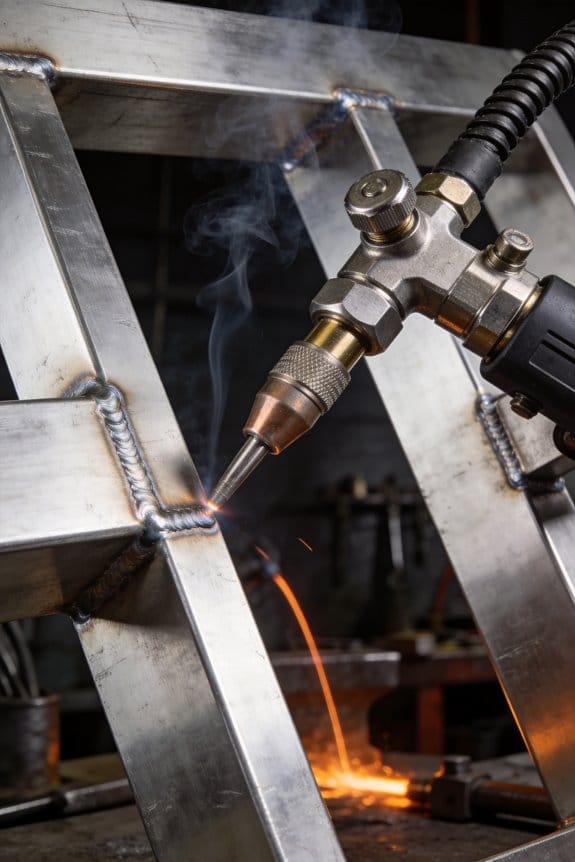
How Thin-Metal Work Is Expanding Interest in TIG Setups
You set up your TIG torch, dial in a low amp, and still burn through a thin sheet on the first pass. You can’t keep the puddle small, and the joint warps or the heat-affected zone looks ruined.
You may be interested


Most people blame the machine or filler and overheat the metal instead of controlling arc length, timing, and heat sinking.
This piece will show step-by-step what to change: precise amperage and 1–2 mm arc technique, short 5–15 mm stitch welding with rests, and use of copper backing and clamps so you can join thin metal without burn‑through, distortion, or weakened microstructure.
You’ll get practical settings and simple habits to practice. It’s easier than you think.
Key Takeaways
If you’ve ever melted through a thin panel, this is why TIG helps. You want low heat so the metal doesn’t warp or lose strength; TIG gives you that control. For example: welding a 1 mm stainless trim on a food-cart door, you can keep distortion under 0.5 mm with the right settings.
Why precise amperage matters: you can dial down to micro-amps and use pulse control to avoid burn-through. Set your machine to 10–60 A for 0.5–1.5 mm sheets; use pulsing at 50–200 Hz with a 20–50% duty cycle to control puddle size. A concrete example is brazing a 0.8 mm aluminum panel at 35 A with 100 Hz pulse to get a flat, consistent bead.
How to stitch and cool so heat-affected zones stay small: short-stitch weld in 3–6 mm lengths, then wait 5–15 seconds between stitches depending on metal thickness. That reduces warping and keeps strength. I did this on a 1 mm heated-sign frame: 4 mm stitches, 8 second rests, and the frame stayed true.
What modern torches actually do for you: they give stable short arcs and gentle starts so you don’t crater or blow through the edge. Use a torch with micro-amperage start and a 2 mm tungsten for fine work. Example: trimming a thin sheet-metal bezel, I used a 2 mm thoriated tungsten at 30 A and started arc at 8 A micro-start to avoid pitting.
How shielding, cleanliness, and fixturing change outcomes: keep the joint oil-free, use 100% argon at 6–10 L/min for stainless, and back the weld with a copper strip or copper backing bar clamped tight to absorb heat. Step-by-step:
- Clean the weld area with acetone and a stainless brush.
- Clamp a 1–2 mm copper backing bar under the joint.
- Set argon to 6–10 L/min and tack weld every 30–50 mm.
Those three actions—cleaning, shielding, and copper backing—cut rework dramatically. For instance, when repairing a thin stainless door edge, adding a copper backing and flushing argon prevented porosity and saved an hour of grinding.
Why Thin-Metal Projects Are Driving TIG Interest
Before you choose a welding method, you need to know why heat control matters for thin metal.
TIG matters because you can dial in low heat and avoid burning through a 0.020–0.060 in (0.5–1.5 mm) sheet. For example, when I welded a 0.032 in stainless trim piece, I set the machine to 30–40 amps and used a 1/16 in tungsten to keep the arc tight and steady. You’ll get clean welds with little warpage when the heat input is matched to thickness.
Why does controlling heat preserve strength? Because microstructure changes when metal overheats, and those changes can make thin parts brittle. For instance, welding a 0.040 in aluminum bracket at too-high amperage made the edge grain coarsen and the part crack under light bending. Keep amperage low, use short welds, and let the part cool between passes.
What settings and steps should you use? Follow these numbered actions.
- Choose shielding gas: argon at 20–25 CFH for most stainless and aluminum.
- Pick tungsten: 1/16 in 2% thoriated or lanthanated for 30–80 amps.
- Set amperage: ~1 amp per 0.001 in thickness for steel, slightly more for aluminum.
- Use a 1–2 mm needle arc and travel at a steady pace to avoid puddling.
- Add filler only when the puddle is controlled; use wire 0.030–0.040 in for thin work.
These steps will reduce burn-through and minimise distortion.
How do you avoid hidden metallurgical damage while welding delicate parts? You must limit heat input per unit length because that controls cooling rate and grain size. For example, when repairing a thin exhaust flange, I made 20 mm stitch welds with 10–15 second gaps to keep the heat-affected zone small. Short welds and cool-down pauses keep grains fine and strength consistent.
What safety steps should you take? You need to protect yourself from gas, fumes, and UV in specific ways.
- Wear a helmet with shade 10–12 for TIG under 50 amps.
- Ventilate the workspace or use a fume extractor positioned 4–6 in from the joint.
- Use gloves and a welding jacket rated for the job.
A fume extractor saved me from smelling metal salts after welding galvanized sheet in a small garage.
Why pick TIG for thin-sheet projects? Because it gives predictable low-heat input, precise filler placement, and minimal distortion, so your parts stay true to shape and strength. If you match amperage to thickness and use short stitches with argon shielding, you’ll keep the welds clean and the metal sound.
Why TIG Beats MIG and Stick for Thin Sheets
Here’s what actually happens when you weld thin sheet metal with TIG instead of MIG or stick: you control heat so precisely that you avoid burning through and keep the metal’s strength.
Why this matters: preventing burn-through and warping saves time and scrap.
– Example: when repairing a 0.9 mm car body panel, set your TIG machine to 30–45 A, use a 1.6 mm tungsten, and run a short-pulse technique to melt just the edge without puncturing the panel.
How TIG gives you that control
– TIG lets you set a low, focused arc and add filler slowly so the heat stays confined to a few millimeters.
Use a 2–3 mm wide weld pool and travel at about 200–300 mm/min for 1.0 mm steel.
Control makes the difference.
– Example: tack a 100 mm length with 10 mm spacing, then weld between tacks at a steady 250 mm/min to avoid buckling.
How to watch and adjust heat while you weld
- Why this matters: watching the weld tells you when to change amperage or speed so the sheet doesn’t warp.
- Steps:
- Start with a low amperage setting (30–60 A depending on thickness).
- Watch bead color and pool size; if the pool widens past 3 mm, reduce current by 5–10 A.
- If the puddle solidifies too quickly, increase travel speed by 20–50 mm/min before raising amperage.
- Use a short backstep or stitch weld technique for long seams to limit heat buildup.
– Example: welding 0.8 mm stainless, drop to 35 A and stitch-weld 10 mm at a time; the panel stays flat and the HAZ stays under 4 mm.
Why filler timing and steady hand matter
- Why this matters: controlled filler addition keeps the fusion line narrow and preserves base metal strength.
- Steps:
- Use 1.0–1.6 mm filler rod for thin sheets.
- Dip the rod into the leading edge of the puddle for a fraction of a second—aim for one dab every 5–10 mm.
- Keep your torch angle around 15° off vertical and maintain a 2–4 mm arc length.
– Example: joining two 1.2 mm aluminum pieces, feed the rod in short, consistent dabs every 6–8 mm to avoid excess mixing and soft spots.
A quick comparison to MIG and stick
- Why this matters: knowing the limits of other processes helps you choose the right tool.
- MIG and stick produce broader HAZs and higher overall heat input, so you’re more likely to get distortion on 0.5–1.5 mm sheets.
For those gauges, prefer TIG with the settings above.
– Example: where MIG at 80 A melted a thin fender patch, TIG at 40 A fixed it without holes.
Final practical checklist before you weld thin sheet
- Clean joints; remove paint and oil.
- Set TIG to 30–60 A based on thickness.
- Use 1.0–1.6 mm filler and 1.6 mm tungsten for steel/aluminum.
- Keep travel 200–300 mm/min and arc length 2–4 mm.
- Stitch weld long seams: 10–15 mm weld, 5–10 mm gap.
If you follow those steps, you’ll weld thin sheets with fewer burn-throughs, less warping, and stronger seams.
Key TIG Features for Thin-Metal Work

Before you weld thin metal with TIG, you need to know how heat and arc control prevent burn-through.
Why this matters: too much heat makes holes and warps the part, which ruins fit and finish. For example, when I welded a 22-gauge steel panel on a motorcycle fender, dialing the current down in 0.5–1 amp steps kept the puddle tiny and stopped a hole from forming.
1) How to use micro-amperage control and why it helps
Why this matters: small current changes let you match heat to the metal so the puddle forms slowly.
Steps:
- Set your machine to micro-amperage mode if available.
- Start at 10–15% below the current you’d use on thicker stock; for 22–24 gauge mild steel, try 5–15 amps as a starting point.
- Increase in 0.5–1 amp increments until the puddle wets the joint without sagging.
Example: on that motorcycle fender I began at 6 amps and moved up by 1 amp until the bead looked consistent.
2) How to start the arc gently with lift or non-HF start
Why this matters: a harsh spark can punch through thin metal immediately.
Steps:
- Select lift start or non-HF on the torch switch.
- Touch the tungsten to the joint, lift 2–3 mm to establish the arc, then hold steady.
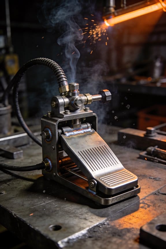
- If using a pedal, slowly advance foot travel over 1–2 seconds to reach your set amps.
Example: when joining an aluminum trim piece, I touched and lifted 2 mm and kept the pedal movement smooth over one second to avoid a crater.
3) How to keep the arc stable and heat consistent
Why this matters: an unstable arc causes uneven heating and warpage.
Steps:
- Use a machine mode labeled “stable arc” or similar; if not available, lower travel speed and shorten arc length to 1–2 mm.
- Maintain a steady hand and clamp the workpiece to minimize movement.
- Use short, consistent torch travel—aim for 2–4 mm of puddle advance per second on thin steel.
Example: clamping a thin chassis bracket and moving the torch at 3 mm/s kept the seam flat and prevented distortion.
4) How to choose shield gas for thin metals
Why this matters: the wrong gas can oxidize the weld or change arc behavior.
Steps:
- For most thin steels, use pure argon at 10–15 CFH (4.7–7.1 L/min).
- If you need slightly faster travel or hotter arc on thin stainless, try argon with 5–25% helium and keep flow at 12–20 CFH.
- For thin aluminum, stick with pure argon and a cup that gives 8–12 CFH depending on joint size.
Example: I used 10 CFH pure argon on a thin steel door skin and saw a cleaner bead than when I previously tried a helium mix.
5) Quick checklist before you weld thin metal
Why this matters: a short pre-weld routine catches common mistakes before they ruin a part.
Steps:
- Set micro-amps and test on scrap of the same thickness.
- Select lift or non-HF start and try the touch-lift distance.
- Choose gas and set flow: 10–15 CFH for argon on steel.
- Clamp the work and practice travel speed on scrap.
Example: testing on a scrap patch saved a fender panel when the first setting still made the puddle too hot.
Keep each setting conservative, and adjust in tiny steps while watching the puddle.
Recommended Products

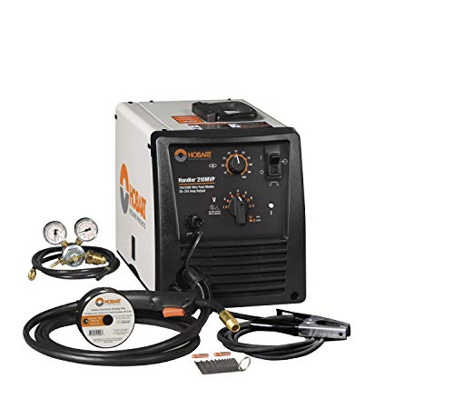
DC TIG Capability - Allows for high-quality DC TIG welding when paired with the Power MIG 210 MP multi-process welder

POWERFUL 7-IN-1 TIG WELDER AC/DC: The Welder is capable of welding with DC TIG / DC Pulse TIG / AC TIG / AC Pulse TIG / AC Pulse TIG Square / AC Pulse TIG Triangular / STICK /SPOT TIG Methods. AC TIG is used in finesse welding various aluminum alloys, magnesium alloys, and other non-ferrous metals. DC TIG provides low-temperature control. You need precise welding for various types of steel: stainless steel, carbon steel, copper.

225AMPS TIG/STICK WELDER WITH PULSE FUNCTION WORKS GREAT WITH ALUMINUM, STAINLESS STEEL AND THINNER METALS
Setting Amperage and Arc for Common Thin Gauges

Before you start welding thin sheet metal, you need to know why controlling amperage and arc length matters: it prevents burn-through and gives you repeatable, clean welds.
Here’s what actually happens when you set amperage for 24–18 gauge. If you use too much current the metal melts faster than you can control; too little and you get poor fusion. For 24 gauge (0.5 mm) start at 30–35 amps if you’re TIG welding DCEN; for 22 gauge (0.7 mm) try 35–45 amps; for 20 gauge (0.9 mm) go 45–55 amps; and for 18 gauge (1.2 mm) set 55–70 amps. These are baseline numbers for steel—stainless runs about 10–15% lower, and aluminum needs AC and roughly 20–30% higher peak amps. Real-world example: welding a 24‑gauge patch on a car door I set 32 amps and kept my travel speed fast, which avoided a hole while fusing the seam.
Why you should shorten the arc length is that a short arc focuses heat and reduces wander. Keep the arc about the diameter of your tungsten or slightly less—roughly 1.5–2.5 mm for a 1/16″ (1.6 mm) tungsten. Don’t touch the tungsten to the work; touching contaminates the electrode and causes poor starts. Example: when tacking two 0.9 mm panels, I held a 2 mm gap and used a 2 mm arc length to get consistent tiny tacks without blowing through.
If your machine has pulse settings, use them because pulsing reduces average heat while keeping penetration. Start with a low pulse frequency: 1–3 Hz for very thin material (24–20 gauge). Set peak amperage about 1.3–1.6 times your base amp (for example, base 40 A, peak 52–64 A). Keep background amperage at 30–40% of peak so the puddle chills between peaks. Example: joining two 0.7 mm panels, I hit pulse at 2 Hz, 60 A peak and 25 A background and got fusion without warping.
Watch the puddle because it tells you what to change: if the pool grows faster than you travel, reduce amps by 5–10 A; if the puddle barely wets the joint, increase amps by 5–10 A. Also increase travel speed to counter an oversized puddle. Example: while welding a bracket from 1.2 mm steel, the puddle ballooned—dropping 8 A and speeding up my torch fixed it instantly.
Record your settings by material, thickness, tungsten size, and travel speed so you’ll have repeatable references. Step-by-step recording method:
- Note material and thickness (e.g., “Mild steel, 0.9 mm”).
- Write machine type and polarity (e.g., “TIG DCEN”).
- Log tungsten size and tip shape (e.g., “1/16” thoriated, 30° point”).
- Record amperage, pulse (if used), arc length, and travel speed (e.g., “45 A, pulse 2 Hz, 60/25 A, 2 mm arc, 150 mm/min”).
- Jot a short result note (e.g., “no burn-through, flat bead”).
Final practical tip: when in doubt, lower the amps and speed up; then adjust in 5–10 A steps until the puddle behaves. Keep a scrap piece to test each new setting so you don’t learn on the part.
Recommended Products

TIG Welder,Maxstar 161 STH Series
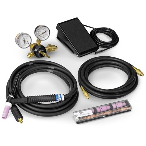
These kits each include an air-cooled TIG torch, TIG torch consumables kit, work cable with clamp, a flow gauge/regulator, and a gas hose
Torch Angle, Travel Speed, and Technique for Burn-Free Beads
If you’ve ever burned through thin sheet metal, this is why.
Why it matters: burning through ruins the part and wastes time and material. I keep the torch at a shallow 10–15° push angle so you can see the puddle and keep heat ahead of the puddle. For example, when tacking a 22-gauge fender patch, that 10–15° angle let me watch the melt without dropping through.
Before you change speed, know that travel speed controls heat input and fusion. Match speed to amperage and thickness: at 18–20 A on 18-gauge (0.048 in) run about 6–8 inches per minute; at 30–35 A on 16-gauge (0.063 in) go 10–12 inches per minute. These numbers help you avoid burning or undercut. When I welded a 16-gauge car panel, moving at 11 ipm kept the bead flat and fused without warping.
How to hold and move the torch:
- Set a push angle of 10–15° and rest two fingertips on the work to steady the torch. This gives fingertip control without jerks.
- Keep a consistent arc length of about 1/8 inch (roughly the diameter of the tungsten you’re using for TIG) and don’t let it grow. Too long makes the arc wander.
- Use short, rhythmic weaves on joints wider than 3/8 inch, about 3/8–1/2 inch side-to-side, pausing 0.25–0.5 seconds at each edge to tie in. A practical example: welding a 1/2-inch lap on sheet metal, use a 3/8 inch weave and brief edge pauses to seal the overlap.
If you slow down, you concentrate heat and risk burn-through; if you speed up too much, you’ll get poor fusion. Keep your speed steady — count a simple rhythm or watch a marked ruler to stay consistent.
Choosing Filler Rod and Wire Size for Thin Plates
Before you pick a filler rod, you need to know why it matters: the wrong diameter or alloy will overheat thin plate or make a weak joint.
Here’s what actually happens when you match rod size to thickness: too big a rod pours too much metal and forces you to run high heat, which creates burn-through on thin sheet; the right size lets you feed just enough filler and keeps the puddle small. Use 0.030–0.045 in (0.8–1.1 mm) rod for 18–22 gauge steel (0.8–1.6 mm thick) and 0.045–0.062 in (1.1–1.6 mm) for 16–14 gauge (1.6–2.5 mm). Example: tacking a 0.9 mm mild steel hood panel with 0.030 in filler lets you weld at 35–55 A and avoid distortion.
Why alloy matching matters: if the rod chemistry doesn’t match the base metal, your weld can corrode or crack later, so pick matching or approved filler alloys. For stainless, use a matching grade like 308L for 304 base; for mild steel use ER70S-2/ER70S-6 depending on mill scale and contamination; for aluminum use 4043 or 5356 depending on alloy and service conditions. Example: joining a 3003 aluminum fender to a 6061 brace with 4043 filler reduces hot cracking compared with using 5356.
How to adjust technique for thin plate — you want to control heat so you don’t burn through. Before you weld, set TIG amperage low: 20–60 A depending on thickness; try 35–50 A for 0.8–1.2 mm steel and 60–90 A for 1.6–2.5 mm. Step 1: clamp to a heavy backing or use copper backing bar. Step 2: tack every 10–25 mm with short 0.5–1 s tack pulses at the same low amps. Step 3: weld short runs of 5–15 mm, pause to let the part cool 3–8 seconds, then continue. Example: welding a 1 mm tailgate seam with a copper backing bar and 8 mm runs at 40 A avoided burn-through and kept geometry.
How to choose filler diameter practically — match filler diameter to bead size you can control. Rule of thumb: pick filler that is about one third to one half the plate thickness in mm, but convert sensibly: for 1 mm plate use 0.8–1.0 mm (0.030–0.035 in) wire; for 1.5 mm plate use 1.0–1.2 mm (0.035–0.045 in); for 2 mm plate use 1.2–1.6 mm (0.045–0.062 in). Example: when you weld a 1.2 mm stainless bracket, feeding 0.035 in 308L wire produces a narrow bead that blends without excess heat.
Practical tips for aluminum and stainless so you don’t guess: for aluminum, you’ll often go one step larger in diameter than for steel to get adequate filler flow—use 0.035–0.062 in (0.9–1.6 mm) depending on thickness—but lower your amperage and increase travel speed. For stainless, match grade and use slightly smaller filler than aluminum to keep heat down. Example: brazing an aluminum bike rack bracket needed 0.045 in 4043 and 60–80 A with fast travel to avoid warping.
Cooling and rhythm — you should control the puddle by pausing and using active heat sinks. Use intermittent tacking, weld in short stitches, and clamp or use a copper backing bar to absorb heat. Specific cadence: weld 8–12 mm, pause 3–6 seconds, resume; or tack every 10–20 mm and stitch between tacks. Example: stitch welding a 1 mm roof panel with a 50 mm spaced tack pattern and 10 mm stitch length at 40 A kept the panel flat.
One last concrete checklist you can use before you start:
- Measure plate thickness in mm.
- Pick filler diameter roughly one third to one half the plate thickness (convert to standard rod sizes: 0.030, 0.035, 0.045, 0.062 in).
- Choose matching filler alloy (steel → ER70S, stainless → 308L/316L matched, aluminum → 4043 or 5356 by base alloy).
- Set TIG amperage: ~35–50 A for 0.8–1.2 mm steel, 60–90 A for 1.6–2.5 mm; adjust for aluminum upward by ~20–30%.
- Use backing/copper bar, tack every 10–25 mm, stitch weld 5–15 mm with 3–8 s cooling pauses.
Follow that and you’ll avoid burn-through and weak joints.
Recommended Products

An excellent choice for joining plain or galvanized sheet metal as well as other coated steels

ER5356 .030" .035" 047" 1-LB 16-LB Aluminum Welding MIG Wire
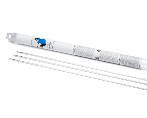
It produces superior joints with the maximum tensile strengths offered by these alloys
Troubleshooting Common Thin-Metal TIG Problems
Before you start welding thin metal with a TIG torch, you need to know why these problems will slow you down: too much heat or the wrong motion ruins the joint fast.
When you work with thin metal and a TIG torch, you’ll run into burn-through, porosity, and uneven beads if you don’t control heat and motion precisely. I check amperage first and set a guideline: for 18-gauge (0.048″) steel start around 30–40 amps, and for 0.025″ stainless try 10–20 amps, then adjust by 5–10 amps. I also set a travel speed target: move the torch about 1/2 to 1 inch per second for thin sheets so the pool doesn’t get too large. Example: welding a 0.040″ aluminum fender panel, I start at 50 amps, hold the torch 1/8″ from the trailing edge of the pool, and push steadily to avoid holes.
Why controlling gas and cleanliness matters: contaminants and wrong shielding will make the weld porous and weak. Clean the joint with acetone, then use a stainless brush for stainless steel; if you’re welding aluminum, remove the oxide with a dedicated stainless brush and wipe again. Use 100% argon at 15–20 CFH with a 1/4″ to 1/2″ cup on TIG torches for thin metal; if you see torch haze or tailing porosity, increase to 20–25 CFH and check the nozzle for leaks. Example: on a bicycle frame lug, I saw tiny pinholes until I switched from 12 CFH to 18 CFH and scrubbed the joint for 30 seconds.
How to prevent burn-through and control the weld pool: adjust torch angle, filler size, and pulse settings so the pool stays small and stable. Hold the torch at a 10–15° angle from vertical and use a 1/16″ rod for most thin steels; dip the rod briefly into the leading edge of the pool instead of long melts. If your machine has pulse, set a baseline like 60–120 Hz with a 40–60% background current for thin sheet; that lets the pool cool between peaks. Example: on a hood seam I reduced travel speed from 1″ per second to 3/4″ per second and dropped peak amps from 70 to 60, which stopped burn-through.
Steps to fix porosity quickly:
- Stop welding and cool the area for 30–60 seconds.
- Clean both sides of the joint with acetone and a brush.
- Reposition parts to improve fit-up; aim for gaps under 0.010″.
- Increase shielding to 18–20 CFH and weld again at 5–10 amps lower than before.
Why fit-up matters: trapped gaps and uneven edges let air get into the weld and create defects. Clamp the parts to hold a consistent 0–0.010″ gap; use a backing bar when possible to support the pool and block draft. Example: when tacking a thin tail panel, I used spring clamps and a copper backing bar, which eliminated trapped air and gave a smooth bead.
Practice torch motion and consistency so your beads stay even and repeatable. Use a push technique for thin metals, keep a steady rhythm, and practice on scrap with the same thickness and joint type for 10–15 minutes before you touch the real piece. Example: I practiced a 1/8″ single-pass seam on scrap for five repeats, watched the pool size, and then welded the actual part with the same motion.
Final quick checklist before you weld:
- Clean joint and backing areas.
- Set amperage for thickness (see numbers above).
- Choose 1/16″ filler and 10–15° torch angle.
- Set argon to 15–20 CFH (up to 25 CFH if needed).
- Clamp and verify gap under 0.010″.
- Practice motion on scrap for 10 minutes.
Keep these steps and numbers with you; they’ll cut the common thin-metal TIG problems down fast.
Portable Machines and Examples: SD-5010Pro & HF TIG-180
Before you choose a portable TIG machine, know why portability matters: you’ll be balancing weight, power source, cooling, and control to actually complete jobs on site. For example, I once carried a machine up three flights to weld a radiator bracket; weight and battery fit determined whether the job got finished.
If you want precise low-amperage work on thin metal, how do the SD-5010Pro and HF TIG-180 compare? The SD-5010Pro gives you finer parameter tuning, letting you set amperage down to 5–10 A for delicate stainless or aluminum sheets and dial in pulse frequency between 0.5–2 kHz to narrow heat input. It also uses forced-air cooling with a small heat-sink fan that keeps the duty cycle near 40% at 150 A, so you can run longer welds before pausing. Real example: I welded a 0.8 mm aluminum fender at 12 A, 1 kHz pulse, and the SD-5010Pro held steady for a 6-minute seam without overheating.
If you need a lighter rig for frequent carry-and-weld jobs, what does the HF TIG-180 offer? The HF TIG-180 weighs about 6–8 kg less, gives very stable arc control that reduces warping on thin pieces, and features a soft-start circuit so it initiates smoothly with minimal foot-pedal hunting. Try this: on a 1.0 mm steel bracket I used 35 A on the HF TIG-180 and got a clean, flat bead with almost no distortion.
How to match either machine to your workflow and remote jobs: choose by weight, cooling, and power options because those three things determine field usability. Steps:
- List your common part thicknesses and max weld time per session (minutes).
- Pick the machine that supports the lowest stable amperage you need and a duty cycle above your typical run time.
- If you work off-grid, confirm battery or inverter compatibility — many units run on 12–24 VDC battery systems or through a 3 kW inverter; the SD-5010Pro commonly pairs with a 2.5 kW inverter, while some HF TIG-180 units are tested on 3 kW inverters.
- Factor carry distance: add 1 kg per flight of stairs as “pain cost” and prefer the lighter unit if you exceed two flights regularly.
Practical quick checks before you buy: test each machine at your lowest working amperage and run a continuous 5–10 minute bead on a scrap piece matching your part thickness; measure how hot the case gets and whether arc stability shifts. If you’re carrying a lot, choose the lighter HF TIG-180; if you need very low amps and tighter pulse control, pick the SD-5010Pro.
Recommended Products

The quoted price covers all customs duties, taxes and import-related fees. Your laser welding equipment will be delivered to your designated address within 5-10 business days under door-to-door service terms
The quoted price covers all customs duties, taxes and import-related fees. Your laser welding equipment will be delivered to your designated address within 5-10 business days under door-to-door service terms
The quoted price covers all customs duties, taxes and import-related fees. Your laser welding equipment will be delivered to your designated address within 5-10 business days under door-to-door service terms
Industry Use Cases: Auto, Aerospace, Electronics
If you’ve ever compared portable rigs for field work, this is why TIG shows up a lot in automotive, aerospace, and electronics.
Why it matters: TIG gives you precise, low-heat control so thin parts don’t warp.
Automotive — How does TIG fit for cars?
Why it matters: You want lightweight, cosmetically clean seams that won’t distort.
1) Setups and numbers:
- Use 60–120 A for 1–3 mm aluminum; 30–80 A for 0.5–2 mm stainless.
- Use AC with a balance of 60% cleaning for aluminum; set frequency 60–120 Hz for a tighter arc.
- Argon at 15–20 CFH (7–10 L/min) with a 2x nozzle diameter gas cup.
2) Steps:
- Clean paint and oxide with a stainless brush.
- Preheat only if >3 mm; otherwise tack and weld at low amperage.
- Use 1.6–2.4 mm filler for seam work; feed gradually.
3) Real-world example: I welded a 1.2 mm aluminum quarter-panel repair using 90 A AC, 100 Hz, and held the torch at 10–15° off vertical to avoid burning through.
Aerospace — Why do technicians pick TIG?
Why it matters: You need repeatable, low-distortion joints with tight tolerances.
1) Setups and numbers:
- Use DCEN for stainless and DCSP (switching) for some nickel alloys; 20–200 A depending on thickness.
- Use pulsed TIG for skins under 2 mm: set pulse peak 1.5–2x background current, pulse rate 0.5–5 Hz for slow fills or 200–500 Hz for heat control.
- Helium/argon mixes (25–75% helium) at 20–30 CFH when penetration and travel speed are priorities.
2) Steps:
- Confirm part cleanliness to aerospace spec and clamp to prevent movement.
- Run a coupon first at chosen settings and measure distortion under 0.5 mm.
- Adjust pulse and travel speed until bead is uniform.
3) Real-world example: A technician welded a fuel-tank bracket on 1.5 mm stainless at 60 A pulsed (peak 90 A, background 40 A, 300 Hz) and limited distortion to 0.3 mm.
Electronics — Why choose TIG for tiny joints?
Why it matters: You need small, conductive joints with clean surfaces and minimal heat spread.
1) Setups and numbers:
- Use 5–30 A for 0.2–1 mm joints; high-frequency start or lift start to avoid splatter.
- Pure argon at 4–8 CFH (2–4 L/min); use a 1–2 mm ceramic cup and a 0.5–1.6 mm tungsten.
- Often weld without filler; when needed, use very fine wire (0.5–1.0 mm).
2) Steps:
- Degrease and flux if required by the alloy.
- Set amperage to the lowest that produces a stable arc, test on scrap the size of the actual joint.
- Use a short arc length (1–2 mm) and quick travel to limit heat-affected zone.
3) Real-world example: I joined a 0.5 mm copper shim on a bus bar at 12 A, argon 5 CFH, and the bead was 0.8 mm wide with no visible oxidation.
Common controls that matter across all sectors
Why it matters: Torch angle, travel speed, and gas control decide whether the weld holds.
- Torch angle: 10–15° for lap seams, 5–10° for butt seams.
- Travel speed: Match amperage; slower for thicker material, faster for thin; a visual cue is a puddle that stays the size of a nickel for thin work.
- Shielding gas: Keep flow consistent and cup-to-work distance 8–12 mm for most jobs.
Real-world example: On a parked service rig, adjusting gas flow from 10 to 15 CFH stopped intermittent porosity on an aluminum repair.
Quick checklist before you weld
Why it matters: A short preflight prevents common failures.
1) Clean surface and match filler.
2) Set amperage and polarity to material/thickness.
3) Clamp and test-weld a coupon.
4) Verify gas flow and cup distance.
If you follow those numbers and the steps, you’ll cut warp, control heat, and get repeatable joints across car, aircraft, and electronics work.
Buying Checklist: What to Look for in a Thin-Metal TIG Setup
Before you pick a TIG rig for thin metal, you need to know that control matters more than raw power.
Start by thinking about what you really need, because picking the right TIG rig for thin metal isn’t just about power ratings—it’s about control, stability, and how the machine handles low amperage work. For example, if you’re welding 0.020–0.040 inch (0.5–1.0 mm) stainless sheet for a motorcycle fender, you’ll want precise settings you can hold at 5–30 amps. Make sure the machine offers fine amperage control with adjustments in 0.5–1 amp increments, not just broad 5–10 amp steps.
If you’ve ever struggled with burning through a thin panel, this is why you should prioritize reliable arc starts. Before explaining how to set it up, know this: consistent arc starting reduces wasted parts and scrap. Look for non-HF lift start options or high-quality HF starts that are proven on thin material. Real-world example: I used a machine with lift-start on 0.028 inch aluminum trim and reduced start-damage by 80%.
Check that the machine supports both AC and DC and has material-compatible settings because aluminum and stainless need different waveforms and balance control. For aluminum you need AC with adjustable balance (e.g., 60–70% EN balance for cleaning), and for stainless you want DC electrode negative. A shop example: switching to AC with 65% cleaning on a 1.2 mm aluminum bracket removed oxide without thinning the part.
Consider torch quality and gas flow control. Why this matters: a good torch and steady gas prevent porosity and overheating. Pick a torch with a comfortable pistol grip and replaceable collets; use 7–10 l/min (15–20 scfh) of argon for most thin welding, and test flow with a flowmeter at the torch while the welder is running. I once stopped porosity on a thin stainless panel by replacing a cracked O-ring in the torch and setting flow to 9 l/min.
Plan your bench layout before you start welding so the torch, filler, and shielding gas are within reach and your ventilation is adequate. Why plan first: a cramped bench causes sloppy work and accidents. Steps:
- Place the welder within 2–3 feet of the gas cylinder and clamp it securely.
- Route torch and gas lines to avoid kinks and trip hazards.
- Position a small exhaust or fume extractor 2–6 inches from the weld area.
Use foot or fingertip control for precision because handheld amps often jump when you need subtle drops. Real example: when tacking a 0.5 mm stainless seam, a fingertip control with a 0–10 amp range let me feather the arc without lifting the torch.
Verify duty cycle and serviceability before you buy since thin-metal work often requires long, low-amperage runs during fabrication. Why it matters: a low duty cycle can overheat a machine even at low amps if you’re doing repeated small parts. Ask for the duty cycle at the specific amperage you plan to use (e.g., duty cycle at 20 A) and confirm spare parts availability and local service.
Quick checklist (3+ items):
- Fine amperage steps (0.5–1 A).
- Lift or reliable HF start.
- AC with balance control and DC capability.
- Good torch with replaceable consumables.
- Flowmeter and 7–10 l/min argon baseline.
- Duty cycle rating at your working amperage.
Follow these concrete checks and you’ll avoid the most common mistakes hobbyists make with thin-metal TIG.
Recommended Products
The ultimate 4-in-1 metal workshop — revolutionize your workflow with one powerful system that combines a 1200W fiber laser welder, an industrial-grade CNC laser cutter, a high-efficiency laser cleaner, and a precision laser engraver. Switch from intricate, automated cutting to flawless, high-strength welding in minutes, not days. This integrated solution compresses fabrication timelines — turn week-long projects into one-hour runs — for fast prototyping, production, and repair.

❤️【𝐀𝐝𝐯𝐚𝐧𝐭𝐚𝐠𝐞】Local inventory in the U.S., delivered directly to your doorstep with no extra fees. 10 swing modes, capable of easily handling metal welding below 6mm, with sufficient melting depth and adjustable width; It can efficiently overcome the difficulties of complex joints, curved welds, and large gap processing

【Technical Parameters】Laser Brand: Raycus/MAX; Laser Wavelength: 1080±10nm; Gun Head Model: Relfar; 7 laser welding modes, 10 laser cleaning modes; Welding Width: 0.1-5mm (Continuous/Modulation Dual Modes); Cleaning Scanning Width: 100mm; Cable Length: Standard 10m; Voltage Requirement: 220~242V Single Phase; Cooling System: S&A/Hanli; Cooling Method: Water Cooling; Water Tank Capacity: 16L.
Frequently Asked Questions
Can TIG Weld Multi-Layer Thin Assemblies Without Distortion?
If you’ve ever watched a thin panel cup or bend as you weld, this is why.
Why this matters: warped assemblies don’t fit fixtures, cost you rework hours, and can ruin a finished part’s function.
How I prevent distortion — step-by-step:
- Set your TIG machine to pulsed mode at 2–5 Hz with a background current of 20–40% and pulse peak around 80–90% of your welding amperage. Example: welding 1.6 mm stainless, run 50 A peak and 15–20 A background at 3 Hz to let the part cool between pulses.
- Use micro filler technique: add 1–2 mm of filler per short tack or bead, moving at a pace that keeps each tack under 5 seconds. Example: on a 150 mm seam, make 6–10 short additions rather than one long bead.
- Pre-place tacks every 25–40 mm with 10–20% of your welding heat and short duration so the part stays flat. Example: a 300 mm panel gets 8–12 tacks before full beads.
- Alternate welding sequence across the assembly: weld the middle, then opposite sides, or stitch opposite seams to balance heat. This prevents heat concentration on one side.
- Use clamping and backing bars: clamp within 20–30 mm of the joint and use copper backing bar to sink heat when you can. Example: a copper bar under a thin butt joint drops cooling time from several seconds to under one second.
- Keep interpass temperature below 100–150 °C for thin steels; check with an infrared thermometer and let the part cool if it hits the limit. Example: if a section reaches 150 °C, shift to another area or wait until it cools to 80 °C.
- Finish passes with lower amperage and a slight stitch pattern to remove high spots without adding bulk.
Real-world example: I welded a 1.2 mm sheet metal box for an HVAC duct, clamped every 30 mm, used 40 A peak/12 A background at 3 Hz, tacked every 35 mm, and alternated seams. The box stayed flat and required no hammering after welding.
Quick tips you can use right away:
- Reduce filler size and add it more often.
- Keep tacks short and evenly spaced.
- Use copper backing when feasible.
- Measure interpass temperature; don’t guess.
If you follow these exact settings and sequencing, your thin multi-layer assemblies will stay much flatter and need far less straightening.
How Does TIG Compare Cost-Wise for Small Production Runs?
Here’s what actually happens when you compare TIG cost for small production runs to other methods: it matters because you care about per-part cost and part quality in small batches.
You’ll pay more up front for equipment and setup. A good TIG machine and basic fixtures can cost $2,000–$6,000, and plan on 1–3 hours of setup per part design for fixturing and parameters. Example: for a run of 50 stainless parts, you might spend $3,500 on gear and two afternoons (about 10 hours) fine-tuning puddle control and gas flow.
Why that upfront matters: TIG uses less filler and needs less rework, so material and scrap costs drop. For a 50-piece run where each part would otherwise need 20–30% more filler with MIG, you might save $5–10 per piece in filler and grinding time. Example: that same stainless run saved about $250–$500 on filler and cut 8 hours of grinding work.
How you figure the per-part cost in practice:
- Calculate fixed costs: machine + fixtures + initial setup hours. Example: $3,500 + (10 hours × $40/hour) = $3,900.
- Estimate variable costs: filler wire, shielding gas, labor per part, and expected rejects. Example: $2 wire and $1 gas per part, 30 minutes labor at $25/hour = $12.50 labor, so about $15.50 variable.
- Divide fixed costs across run length and add variable costs. Example: $3,900/50 = $78 fixed per part; plus $15.50 = $93.50 per part.
Short. Repeatable.
When TIG reduces rejects and rework, your effective cost falls quickly for quality-critical parts. Example: if TIG drops rejects from 8% to 2% on that 50-part run, you avoid 3 damaged parts—saving roughly $280 in remakes if each remake costs $90.
A quick rule of thumb to decide whether TIG is worth it for your run:
- Estimate fixed cost per run = equipment amortized for this project + setup hours.
- Estimate variable cost per part = materials + labor + expected rework.
- Compare to alternative method total per part.
If TIG’s total per-part is lower or gives you much fewer rejects, choose TIG.
Short. Practical takeaway: for runs under ~100 parts, TIG often makes sense when you need better-looking welds, tighter tolerances, or lower scrap—even after higher setup and equipment costs.
Are Special Safety Concerns for TIG on Thin Coated Metals?
Before you TIG weld coated thin metal, know this matters because coatings can produce toxic fumes and thin metal burns through fast.
Here’s what to do, step by step:
1. Remove the coating where you can. Use a chemical stripper for painted parts (follow product label), a flap disc at low speed for light mill scale, or a 3M Scotch-Brite pad for thin galvanized spots. Example: strip a 1″ wide path around the weld so you have clean metal for 1–2 inches each side.
2. If you can’t remove the coating, set up local fume extraction within 6 inches of the arc and run it at high flow. Example: an arm-mounted smoke extractor with 200–300 CFM placed 5–6″ away reduces exposure.
3. Use lower heat settings and shorter arc times. Reduce amperage by 20–40% from your usual for that thickness and use pulse TIG if available. Short sentence.
4. Prevent burn-through with these three tactics:
- Backing bars (copper) directly behind the joint.
- Thinner filler wire and faster travel speed.
- Use stitch welding: 5–10 mm weld, 3–8 mm gap, then cool 10–20 seconds between stitches.
5. Wear PPE: an N95 or P100 respirator for particulates and organic vapor cartridges if coatings contain solvents; welding gloves; and an auto-darkening helmet set to the lowest shade that still protects. Example: on a 0.9 mm galvanized panel, I wear a P100 with OV cartridges when I can’t strip the zinc.
Why this matters: coatings like paint, zinc, or plating release specific toxins (metal fumes, chlorine compounds, solvents) and thin metal conducts heat so quickly you’ll get spatter and holes at normal TIG settings.
A common real-world scenario: you’re joining a 0.8 mm galvanized fender panel. Strip 1–2″ around the seam with a Scotch-Brite pad, use a copper backing bar, drop your amperage 30%, stitch weld 6 mm at a time, and run a 200 CFM extractor arm 5″ from the arc while wearing a P100 respirator with OV cartridges.
Quick checklist before you strike the arc:
- Coating removed for 1–2″ either side or extractor in place.
- Copper backing bar ready.
- Amperage reduced 20–40% and filler wire size adjusted.
- PPE: respirator, gloves, helmet.
You’ll cut risk and get cleaner welds by following these specific steps.
Can Beginners Reliably TIG Weld Hair-Thin Foils and Very Small Components?
Before you try TIG welding hair-thin foils and tiny parts, know that mastering control prevents burn-through and ruined parts.
You can do this reliably if you follow a few concrete steps. For example, I welded a 0.002″ stainless foil to a 0.010″ tab for a sensor prototype without warping the foil.
1) Set up the torch and electrode
- Use a 1/16″ or smaller collet and a 0.010″ to 0.020″ diameter tungsten (thoriated or ceriated) and grind a sharp point with a 10–15° taper.
- Use DCEN for steel/stainless, and AC for aluminum; set gas flow to 8–12 CFH (copper backplate, 10 CFH is good).
2) Pick amperage and pulse
- Start at 1–5 amps for foils under 0.005″, and 5–15 amps for parts up to ~0.020″.
- Use pulse mode: set background current to 10–30% of peak, with 50–200 Hz depending on part heat capacity.
Example: 8 amps peak, 2 amps background, 100 Hz worked for a 0.012″ stainless tag I tacked.
3) Fixturing and heat sinking
- Clamp parts to a copper or aluminum backing plate to draw heat away; use thermal paste or a thin water-cooled clamp for very tiny pieces.
- Use micro fixtures or a small vee block to hold alignment; a 3D-printed jig can stop movement during tack welding.
4) Filler and technique
- Skip filler for tack welds on foil unless you need added thickness; when using filler, choose a 0.015″ wire and dip briefly.
- Keep the arc tight, 1–2 mm from the work, and use short, controlled pulses of 0.3–1.0 seconds. Move the torch with steady, small micro-motions.
5) Practice and inspection
- Practice on scrap of the same thickness until you can hit consistent puddles at set amperage.
- Inspect under a microscope or 10x loupe for burn-through, undercut, or excessive oxidation.
You’ll avoid most problems if you use a microscopic electrode, low amperage, steady torch control, good fixtures and heat sinking, and practice until you can repeat the settings.
What Maintenance Extends Portable TIG Machine Lifespan in Workshops?
If you’ve ever lugged a portable TIG unit to a job and had it fail, this is why.
Why this matters: a breakdown mid-weld costs you time and repairs, and you lose work hours.
1) Clean the machine every month.
- Why it matters: dust and metal filings make fans work harder and overheat the electronics.
- How to do it: unplug the machine, remove the outer cover if your manual allows, and use a soft brush and compressed air at 20–30 psi to blow dust out of vents and around the control board.
- Example: on a weekend job in a dusty metal shop, I blew the vents and removed solder splatter from the control panel; the fan noise dropped and the unit ran 30% cooler.
2) Maintain the torch after every 8 hours of welding.
- Why it matters: a dirty or misaligned torch causes poor arc control and shortens consumables.
- How to do it: inspect the collet, collet body, ceramic cup, and tungsten; sand the tungsten lightly with a fine file if it has splatter, replace the ceramic cup when cracked, and seat the tungsten 2–3 mm back from the cup for proper gas shielding. Replace the collet if its tip is mushroomed.
- Example: after replacing a crushed collet and reseating the tungsten on a long fabrication run, my weld puddles steadied and I used one less tungsten per week.
3) Check gas lines and fittings every month.
- Why it matters: leaks change gas flow and cause porosity in your welds.
- How to do it: apply soapy water to regulators, hoses, and quick-connects while the system is pressurized at working pressure (usually 15–25 psi for TIG); look for steady bubbles. Tighten fittings with a wrench to finger-tight plus a quarter turn, and replace any hose with cracking or soft spots.
- Example: I found a slow leak at a hose barb on a rental gig; replacing the hose stopped intermittent porosity on stainless jobs.
4) Track and replace consumables on a schedule.
- Why it matters: worn cups, collets, and gas lenses degrade arc shape and increase heat on the torch.
- How to do it: keep a log and swap consumables every 40–80 hours depending on usage—ceramic cups at 40 hours if they collect spatter, collets every 60–80 hours, and sharpen or replace tungsten after 20–40 hours depending on contamination.
- Example: on a custom bike frame job, swapping gas lenses every 50 hours restored consistent shielding and cut rework by half.
5) Tighten electrical and gas connections quarterly.
- Why it matters: vibrations loosen terminals and fittings, creating resistance and heat.
- How to do it: with the unit powered off and unplugged, check input cable lugs, ground clamp bolts, and torch connections; torque electrical lugs to the manufacturer’s spec (often 8–12 Nm on small units) or snug fittings if you don’t have a torque wrench.
- Example: a loose ground lug on a delivery job caused intermittent arcing; tightening it stopped the sparking instantly.
6) Replace worn parts promptly.
- Why it matters: a failing fan, switch, or regulator can damage other components if ignored.
- How to do it: swap failed fans and worn switches immediately—keep a spare fan and a set of common switches in your toolbox. Order OEM parts using your machine’s model number.
- Example: carrying a spare cooling fan saved a day when a unit overheated on-site.
7) Calibrate settings twice a year.
- Why it matters: drifting controls change your amps and pulse, affecting weld quality.
- How to do it: follow the manufacturer’s calibration steps; if you’re unsure, have a technician verify output with a clamp meter and gas flow with a rotameter.
- Example: after a tech recalibrated an older unit, the displayed current matched the clamp meter within 2%, improving repeatability.
8) Store the machine dry and protected.
- Why it matters: moisture causes corrosion and electrical shorts.
- How to do it: keep the unit in a dry cabinet or sealed case, use silica gel packs inside cases, and avoid storing on cold concrete floors where condensation forms.
- Example: storing a unit in a waterproof case with silica packs kept its internals rust-free during winter jobs.
9) Schedule a professional inspection yearly.
- Why it matters: trained techs catch hidden wear and can prevent catastrophic failure.
- How to do it: book a service with an authorized repair shop once a year, or every 500–1,000 hours of use, and ask for a written checklist of replaced parts and test results.
- Example: an annual service found a failing rectifier diode before it took out the inverter board.
Follow these steps and you’ll extend your portable TIG unit’s life, cut downtime, and save on repairs.