As an Amazon Associate, we earn from qualifying purchases. Some links on this site are affiliate links at no extra cost to you. Our recommendations are based on thorough research and editorial judgment.
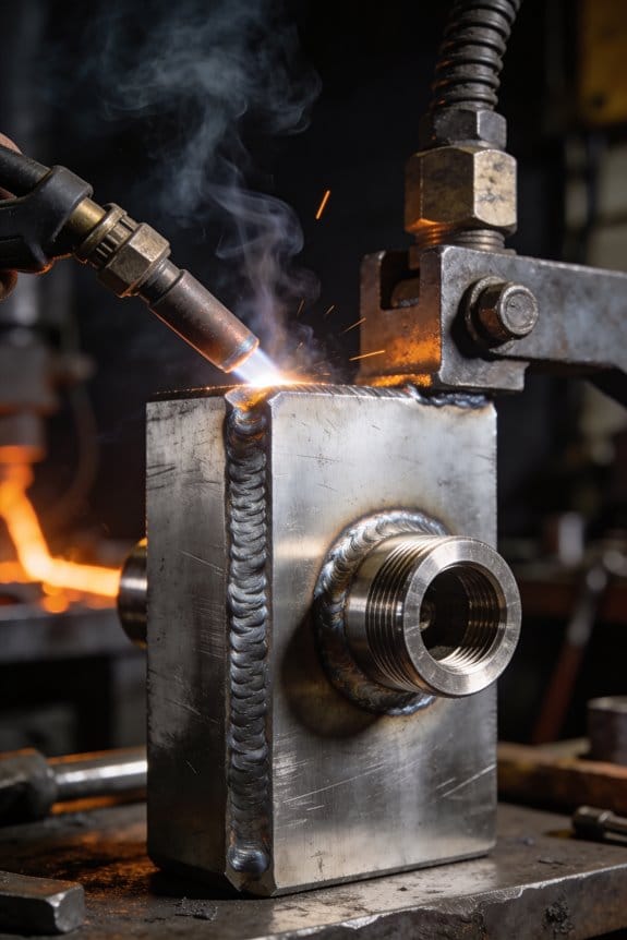
How TIG and MIG Are Being Compared in Modern Workflow Content
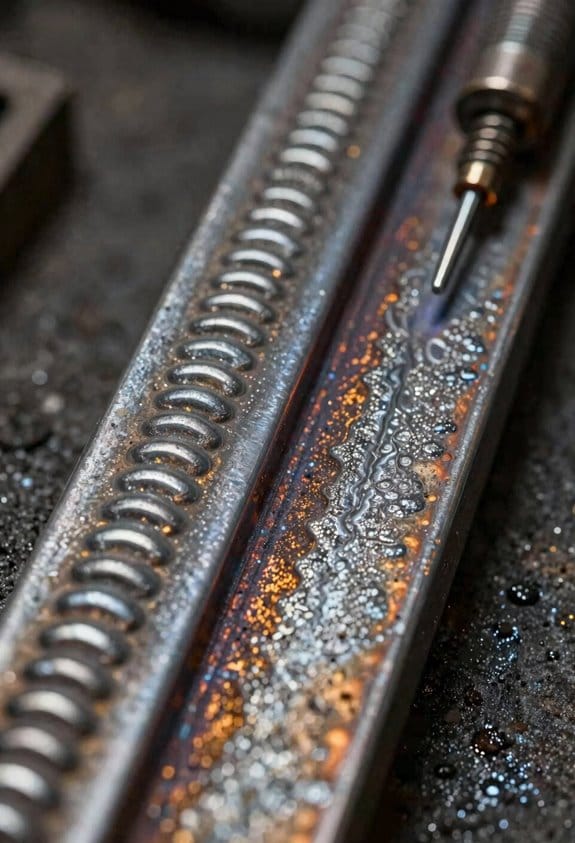
You’re staring at two parts on the jig and can’t decide: should you MIG for speed or TIG for a clean seam? That split-second choice — speed versus finish, outdoor tolerance versus thin-alloy control — is the exact problem here.
You may be interested


Most people default to one process based on habit or a half-remembered rule, not the actual job requirements. This article shows you, step by step, how to match MIG or TIG to each specific job: the exact conditions, material thickness, and finish you need, plus the tooling and transfer modes to use so your welds meet specs.
You’ll get clear, actionable checklists and examples. It’s simpler than it looks.
Key Takeaways
If you’ve ever stood over two welding machines and wondered which to pick, this will help.
– TIG gives you fine control and a cleaner look, but it’s slower; MIG throws down welds fast and is better for high-volume work. Example: when you’re restoring a vintage motorcycle tank that will be visible, use TIG at 70–100 A with pure argon and a 1.6 mm tungsten for neat, thin-penetration beads. For a garage-built trailer frame, set MIG to 18–22 V and 250–300 IPM with a 0.035″ ER70S-6 wire for quick, strong seams.
Before you choose, know what matters: environment, speed needs, and material thickness determine the right process.
- Use TIG for thin sheet, visible joints, or exotic alloys like stainless or aluminum; it’s the go-to when you need a polished finish. Real example: repairing a stainless kitchen island corner—TIG at 80 A, filler ER308L, and small 1/16″ torch tip keeps heat low and minimizes warping.
- Use MIG for thicker, structural, or outdoor work where speed and throughput beat cosmetics. Real example: welding a 3/16″ structural plate on an outdoor gate—MIG at 22 V, 300 IPM, and CO2/argon mix gives deep penetration and holds up to weather.
Here’s why the quick decision frameworks matter: you can pick the right tool fast and avoid wasting time or material.
– Quick decision steps:
- Check thickness: under 3 mm → TIG; over 3 mm → MIG.
- Decide finish: visible seam → TIG; hidden/structural → MIG.
- Consider environment: indoor, clean → TIG; outdoor/windy → MIG with flux-cored wire.
Example: you have a 2 mm aluminum sign bracket to make at a busy shop—step 1 sends you to TIG with 120 A, pure argon, and a 1.0 mm filler rod.
Before you set up machines, see specific parameters, consumables, and tooling examples so you don’t guess.
– Practical setup examples:
- TIG (thin steel): 50–120 A, pure argon, 1.6 mm thoriated/lanthanated tungsten, 2% lanthanated recommended, 1/16″ torch cup.
- TIG (aluminum): AC 80–200 A, balance control 60/40 *cleaning/penetration*, 3/32″ tungsten, filler 4043 or 5356.
- MIG (mild steel): 18–24 V, 200–350 IPM, 0.030–0.045″ wire, ER70S-6, 75/25 Ar/CO2 gas for spray or short-arc settings.
- MIG (flux-cored for outdoors): 0.035″ flux-cored wire, 23–26 V, 300–350 IPM, self-shielded if windy.
Example: building a pickup bed rack—use MIG with 0.045″ ER70S-6, set 24 V and 320 IPM for 1/4″ tubing.
The difference between TIG and MIG comes down to balancing quality versus efficiency.
– Best practice: use a hybrid workflow to save time and keep looks where they matter.
- Fit and tack with MIG for speed: tack at 2–3 spots per joint, 0.5–1.0 in apart.
- Finish visible seams with TIG for appearance: run TIG beads over exposed joints at appropriate amperage.
Example: fabricating a bike frame—MIG-tack all joints quickly, then TIG the top tube where the paint will show.
Follow these steps and you’ll match process to need, avoid rework, and get predictable results.
Quick Recommendation: When to Choose TIG vs MIG
Think of choosing a welding method like picking a tool for a job: one tool is faster, the other gives cleaner detail. You want the right tool for the metal, the appearance, and the time you have.
Why it matters: choosing the wrong process wastes time and can ruin the finish.
Example: welding a thin aluminum bike frame on your garage bench—if you pick the wrong process, you may burn through the tube.
When should you pick MIG?
- Why it matters: MIG saves time and labor when you have lots of metal to join.
- Steps to decide:
- Use MIG when you need speed: set wire feed to 300–450 inches per minute for mild steel around 1/8″–1/4″ thickness.
- Use a shielding gas mix like 75% argon / 25% CO2 for cleaner seams on mild steel.
- For repairs or production, run short-circuit transfer for thin parts and spray transfer for thicker sections above 3/16″.
- Real-world example: fixing a 3/16″ steel trailer frame in your driveway — MIG with 0.035″ wire and 75/25 gas will lay bead quickly and let you finish in one afternoon.
- Practical note: MIG tolerates dirt and rust better than TIG, but you’ll get more spatter.
When should you pick TIG?
- Why it matters: TIG gives you control and a nicer-looking weld when appearance or thin materials matter.
- Steps to decide:
- Use TIG for thin metals (under 1/8″) and exotic alloys like stainless, titanium, or aluminum.
- Set amperage so that each 0.001″ of stainless takes roughly 1 amp (e.g., 100 amps for 0.100″ stainless).
- Use 100% argon for shielding on aluminum and stainless, and clean the joint first with a stainless brush.
- Real-world example: building a stainless kitchen handrail — TIG at 70–90 amps on 1/16″ tube gives smooth, mirror-like beads that look professional.
- Practical note: TIG needs both hands and steady rhythm; expect slower cycles and more fatigue.
Material checklist (quick):
- Thin sheet or exotic alloys → TIG.
- Common mild steel, thicker sections, or speedy repairs → MIG.
- Aluminum thicker than 1/8″ can be MIG with spool gun; thin aluminum needs TIG.
Ergonomics and budget
- Why it matters: your comfort and wallet affect consistency.
- Steps to decide:
- If you work solo in a small shop and need fast throughput, pick MIG; budget for a good gas supply and wire spools.
- If you want premium finish and have more time, pick TIG; budget for a foot pedal, filler rods, and a clean workspace.
– Real-world example: a one-person hobbyist doing weekend projects — MIG for fences and frames, TIG for decorative handrails.
Final practical tip: match method to priority—if speed is top, use MIG settings above; if appearance or thin alloys matter, use TIG settings above. Follow the steps and you’ll avoid common mistakes like burning through thin metal or ending up with a rough, spattery seam.
Recommended Products
Premium Quality: Mig Welding Wire ER70S-6 adheres to AWS A5.18-05 standards, ensuring top-notch quality and performance.

Do Your Best Work ... Color all your clients impressed with the precision and arc control of the ER70S-6 solid MIG welder wire. You'll love the low splatter whether you're performing single or multi-pass welds. Great for T-joints, butt welds & lap welds.
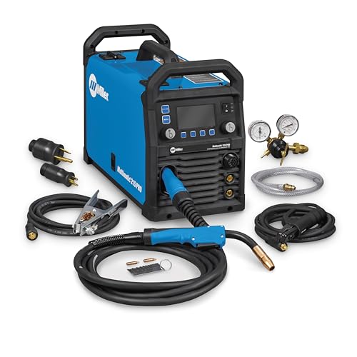
Versatile Performance — Pulsed MIG & Pulsed TIG: This multiprocess welder handles MIG, Pulsed MIG, TIG, Pulsed TIG, and Stick; Auto-Set provides fast settings; powered by continually upgradable USB software
Decision Framework for TIG vs MIG

If you’ve ever stood over two different welders and had to pick one, this will make it simple. You need the right process because it changes cost, finish, and how fast you hit deadlines.
Which environment should you pick for? Answer: the work site. If you’re welding outside or in a drafty bay, choose MIG with a gas like C25 (75% argon / 25% CO2) or use 0.035″ flux-cored wire so wind won’t blow your shield gas away. Example: welding a steel fence on a windy day — set your MIG at 18–24 volts and 200–260 IPM wire feed for 0.035″ ER70S-6 on 3/16″ material. This keeps your bead consistent.
Why care about production vs precision? Because time and appearance trade off directly. For high-volume fab work, go MIG: you can lay down welds 2–4 times faster than TIG on the same joint. Example: assembling chassis rails for go-karts — use MIG at 120–200 amps and a 0.045″ wire to hit cycle targets. If the part is visible or metal is thin (under 1/8“), use TIG for cleaner finish and better control of heat input. Example: repairing a 0.060″ aluminum bike frame tube — TIG at 70–100 amps with a 1/16″ filler rod and pure argon will avoid burn-through.
How should you plan maintenance? You should schedule it. TIG torches need lens, O-rings, and cup checks every 40–80 hours of use; keep a spare ceramic cup size and a 2% argon leak check kit on hand. Example: shop doing stainless exhausts replaces TIG consumables every week when running two torches, preventing arc stops mid-job. For MIG, inspect the wire path, contact tip, and liner every 8–16 hours depending on dusty conditions; have extra contact tips in sizes .023″, .030″, and .035″ ready.
What about ergonomics and tooling? You want tooling that reduces fatigue because that improves seam consistency. Use a TIG torch with a flexible head and a long, braided cable if you’re doing overhead work; for MIG, choose a spool gun when welding aluminum to avoid bird-nesting in the feed. Example: a tech doing long seams on trailer beds switched to a push-pull spool gun and cut rework time by half.
Can you combine speed and accuracy? Yes — consider hybrid automation. Use a simple tractor or CNC rotary fixture to hold parts, then weld with TIG for the visible seams and MIG for the structural seams. Example: a shop welding hood hinges runs a MIG from the robot for the back welds at 300 IPM and a manual TIG for the face welds at 90–120 amps for the visible side.
Step-by-step decision checklist you can print and use:
- Check environment: outdoor/drafty → MIG with flux-cored or C25 gas; enclosed shop → TIG OK.
- Identify throughput need: high volume → MIG; visible/thin/critical metallurgy → TIG.
- Specify consumables: pick wire/rod diameter and gas (e.g., 0.035″ ER70S-6 with C25; 1/16″ 4043 filler with pure argon).
- Schedule maintenance: TIG checks every 40–80 hours; MIG checks every 8–16 hours.
- Pick tooling: spool gun for aluminum, flexible TIG torch for awkward angles.
- Evaluate automation: split TIG for finish welds, MIG for structure if batch sizes justify fixtures.
Follow these steps and you’ll pick the right process without guesswork.
Recommended Products

Multi-Process Capable - Welds MIG, Flux-Cored, Stick, and AC/DC TIG.
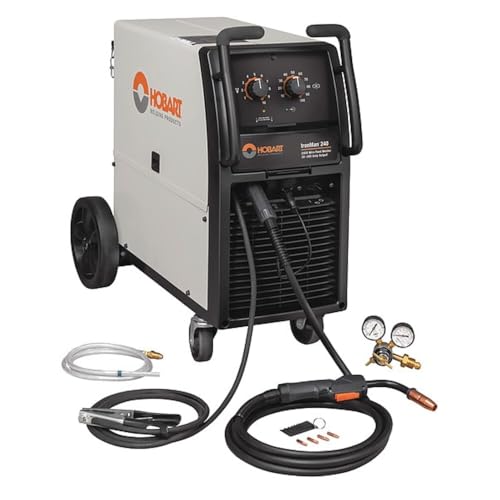
Made in United States

Multi-Process Capable - Welds MIG, Flux-Cored, Stick, and DC TIG.
Operator Skill: Who Should Use TIG vs MIG

Think of choosing a welding process like picking the right tool for a repair: the wrong one makes the job harder and the result worse.
Picking the right process also means matching you to the job, so here’s who should use TIG versus MIG. Before explaining how to pick, know why this matters: matching process to skill saves hours of practice and prevents ruined parts.
TIG for fine, precise work
- Why it matters: TIG gives much cleaner, stronger-looking welds on thin metal, which reduces grinding and rework.
- Who should use it: you if you have steady wrist control and patience. Try this simple check: can you hold a pencil steady for 30 seconds while moving it in tiny circles? If yes, your hands are likely steady enough.
- Real example: welding a 1.0 mm stainless sheet for a motorcycle gas tank filler neck—TIG at 70–90 amps with a 2% thoriated or ceriated tungsten and ER308 filler yields a smooth, narrow bead without burn-through.
- Steps to get started:
- Set AC or DC depending on alloy (AC for aluminum, DCEN for steel), and start at 70–100% pedal sensitivity.
- Use a 1.6–2.4 mm filler rod and keep travel speed slow, about 1–3 inches per minute on thin sheet.
- Practice 15 minutes daily on scrap matching the material thickness.
– Trade-off: TIG requires more practice hours but gives high precision and minimal cleanup.
MIG for speed and larger sections
- Why it matters: MIG lets you lay beads quickly and handle thicker parts without juggling filler rod and torch separately.
- Who should use it: you if you need production speed, have to weld 1.5 mm and up, or want a semi-automatic feed to reduce hand coordination demands.
- Real example: repairing a 3 mm steel bumper on a pickup—MIG at 150–220 amps with a 0.9 mm flux-cored wire or 0.8–1.0 mm solid wire and CO2 mix will fill gaps faster and keep the job moving.
- Steps to get started:
- Choose wire diameter for thickness (0.8 mm for 1.5–3 mm, 1.0 mm for 3–6 mm).
- Set voltage per chart (e.g., 18–20 V for 0.8 mm at 150–200 ipm).
- Practice stringer beads for 10–20 minutes, then progress to weaving if needed.
– Trade-off: MIG is more forgiving and faster but can leave more spatter and requires more grinding for cosmetic finishes.
Apprenticeship pathway and decision checklist
- Why it matters: following a sensible learning order saves time and builds transferable skills.
- Real example: many shops put apprentices on MIG for three months to learn joint prep and bead shape, then add TIG when they must weld thin brake lines or stainless fittings.
- Steps to decide:
- Identify material thickness: under 1.5 mm → prioritize TIG; 1.5 mm and up → start with MIG.
- Assess job priority: cosmetic/precision → TIG; speed/volume → MIG.
- Estimate training time you can commit: <50 hours → get competent with MIG; 100+ hours → aim for TIG competency.
– Quick tip: if you only have to do occasional thin-sheet repairs, rent or borrow a TIG setup and practice 20–30 hours rather than committing immediately.
If you’re deciding, consider job complexity, material thickness, and your available practice time. Start with MIG to build core welding instincts, then add TIG for thin metals and finish work when you can devote focused practice.
TIG vs MIG: Speed, Throughput, and Productivity

Here’s what actually happens when you pick TIG versus MIG for a job: you trade speed for control or control for speed. Why that matters: it determines how many parts you finish per shift and what defects you’ll see.
MIG is built for pace. With MIG you feed wire continuously at, say, 300–600 inches per minute and can hit deposition rates of 5–20 lb/hr depending on wire size and material. For example, on a 1/8″ mild steel panel you can run 0.030″ solid wire at 400 ipm and finish seams in a third of the time compared with TIG. If you want to boost throughput, integrate a robot arm that welds 500–1,000 mm/sec travel speeds and cycles parts without breaks.
TIG trades speed for precision. TIG requires you to add filler manually (or dip with a torch) and control heat carefully to avoid warping; typical TIG deposition is 0.5–5 lb/hr. For example, welding a thin 0.040″ stainless bracket, you’ll run 40–80 A, move at 4–8 inches per minute, and use a tight arc length to avoid burn-through. That slower, steadier approach prevents distortion and gives cleaner beads.
How to lower cycle time with MIG (three steps):
- Standardize parameters: set wire feed to a range (e.g., 350–450 ipm) and voltage to match thickness (e.g., 18–22 V for 1/8″ steel).
- Use continuous fixtures so you don’t reposition parts between passes.
- Automate where possible—add a simple positioner or a robotic cell to reduce operator hours from four per shift to one.
How to keep quality with TIG (three steps):
- Control heat: use pulse or lower amperage and keep interpass temperatures below a setpoint (for stainless, under 250°F).
- Prepare parts: clean joint surfaces with acetone and set fit-up gaps to 0.010–0.030″ for small joints.
- Train for consistency: have operators practice a 6-inch test bead at target amps before starting production.
Practical tip on sequencing and idle time: plan weld order so the torch moves in one continuous direction around a part; that cuts repositioning by up to 40%. Example: when welding a rectangular frame, do all outside seams first, clamp, then finish internal seams without re-clamping.
One last concrete productivity move: measure parts-per-hour for a typical job—run three timed trials, average the results, then change one variable (wire speed, fixture, or automation). Repeat and track percent improvement; you’ll usually see MIG improvements of 20–60% with modest automation, while TIG improvements hinge more on operator skill and fixturing.
Recommended Products

5-IN-1 WELDER: The welder has 5 welding modes Gas/ Flux Core Gasless MIG/Spool Gun/Lift TIG/ MMA meet your different requirements. It is perfectly managed MIG welding of carbon steel, stainless or even thicker steel, Ideal for home DIY, outdoor repairs, rusty metal, farm and road equipment, and maintenance and repairs

MULTI-FUNCTIONS: 6 in 1 Welder, capable of MIG/Pulsed MIG/Flux Core/Spool Gun MIG/Lift TIG/Stick (additional lift TIG torch and spool gun required). This unit caters to a wide range of welding applications and meets your various welding needs.

6-IN-1 WELDER & CUTTER: Outfit your entire shop for the price of one machine. MCT-520 multiprocess machine features 6 working modes: Gas MIG/Flux Core MIG/CUT/HF TIG/MMA/Spool Gun Aluminum Welding (Spool gun sold separately). This versatile welder covers all your project demands—from home DIY and garage projects to outdoor maintenance, farm equipment, and on-site fabrications.
TIG vs MIG: Precision and Cosmetic Finish
The difference between TIG and MIG comes down to how much control you want over the weld.
Why it matters: control affects how the joint looks and whether the part warps. I use TIG when I need precise, tidy beads you can leave visible. For example, welding a stainless-steel handrail with 1/8″ wall tubing, I run TIG at 70–90 amps and feed filler by hand so the bead stays narrow and shiny. Steps: 1) Clean the joint to bright metal. 2) Set the machine to DCEN (if using steel) and 70–90 A for 1/8″ tube. 3) Hold a steady 3–5 mm arc and add thin filler rods. 4) Move at about 10–15 cm/min for a uniform bead.
Why it matters: speed changes job cost and finish. MIG is faster but leaves a bigger bead and usually more spatter, which often needs grinding to look like TIG. Picture a 3 mm mild-steel chassis panel where you need lots of welds quickly; I’ll run MIG at 200–250 IPM wire feed and 18–22 V to push metal quickly and get acceptable strength. Steps: 1) Fit a 0.030″ ER70S-6 wire for general fabrication. 2) Set wire feed to 200–250 inches per minute and voltage to 18–22 V for 3 mm panels. 3) Use a 10–12 mm stickout and a 45° push angle. 4) Grind or flap-disc the seams if you need them smooth.
When to pick which matters because thin parts heat and warp differently. For thin sheet under 1.5 mm, use TIG at lower amps (20–60 A) and small filler or pulse settings to avoid burn-through. Example: repairing a car body panel, I set TIG to 30–40 A and use a 1.6 mm rod to keep holes from forming.
Technique beats gear sometimes: even with the right machine, your final look depends on steady travel speed, correct arc length, and clean base metal. A quick checklist: 1) Clean surface. 2) Match amperage to thickness. 3) Keep arc length consistent. 4) Finish with appropriate grinding or brushing.
Recommended Products

Weldpro's flagship 250 amp version of our extremely popular AC/DC TIG welder that goes beyond simply welding steel and aluminum and is ready for the welding demands of thicker metals. Electrical plug configuration is NEMA 6-50.

Powerful 6-in-1 Aluminum TIG Welder : This TIG Welder supports AC TIG /AC Pulse TIG /DC TIG /DC Pulse TIG /SPOT TIG /STICK welding modes. This multiprocess welder is perfect producing superior welds on materials like aluminum, stainless steel, carbon steel, iron and more. The TIG250AC tig welder can weld penetration 0.5MM-5MM (1/5“-1.97”) aluminum and 0.5MM-10MM (1/5“-3.94”) metals.

309LSI is a great choice when cosmetic appearance is important
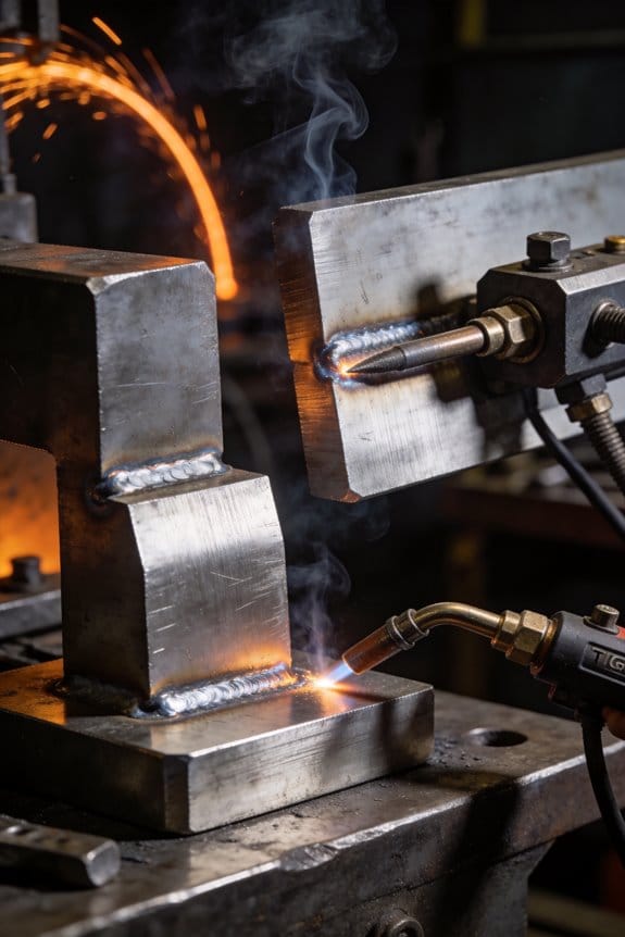
TIG vs MIG: Joint Strength and Metallurgical Differences
The difference between TIG and MIG comes down to how heat is applied and how the metal cools.
Why this matters: the way you apply heat controls grain size, defects, and residual stress, which affect how a joint behaves under load. Example: welding a 3 mm stainless steel bracket for a bike rack shows this — if you use TIG slowly the bead looks smooth and the bracket bends before it breaks; if you use MIG fast, the bead is wider and the bracket can crack near the weld if you overheat it.
How TIG usually gives stronger joints for thin parts
Why this matters: slower, focused heat produces finer grains and fewer inclusions, so the metal stays tougher. Example: when you TIG-weld a 2–4 mm aluminum panel at 60–120 A with a 1.6 mm filler and a 2–3 mm tungsten, you get a tight, narrow fusion zone and visible, fine ripples.
Steps to get that TIG benefit:
- Set amperage to roughly 15–25 A per mm of thickness (so 60–100 A for 4 mm).
- Use 2% thoriated or ceriated tungsten at 1.6 mm for steel, and purge stainless with argon at 5–10 L/min.
- Travel at a steady pace so the pool is small — about 2–4 mm wide — and pause to let the heat sink if the part warms up.
Takeaway: finer grains, cleaner metallurgy, lower residual stress.
How MIG behaves and when it’s fine for your job
Why this matters: MIG deposits metal faster and makes a bigger melt pool, which cools differently and can produce coarser grains that still hold up in many uses. Example: running MIG on a 6 mm mild steel frame at 120–180 A with 0.9 mm wire creates wider beads and faster build-up, ideal for structural subframes you’ll grind later.
Practical MIG settings and technique:
- Choose wire diameter: 0.8–1.2 mm for 3–8 mm steel, set voltage per your machine chart.
- Use short-arc for thin sheet or spray transfer for thicker sections (spray needs >200 A).
- Keep a consistent push or pull angle (10–15°) and weave no wider than 8–10 mm to control heat input.
Takeaway: faster deposition, more heat, manageable with correct parameters.
Residual stress and cooling — what you should do
Why this matters: residual stress influences cracking and distortion, so controlling heat and cooling saves you rework. Example: tack-welding a 200 x 200 mm steel plate in a pattern (center, corners, midpoints) and then finishing reduces warping versus welding one long seam.
Specific actions to lower residual stress:
- Use intermittent welds or stitch welds for long seams: 25–50 mm weld, 25–50 mm gap.
- Preheat mild steel 50–200°C for thicknesses above 10 mm; for alloy steels follow the manufacturer chart.
- Cool slowly if possible — clamp parts and let them cool under insulation or in still air.
Takeaway: controlled heat input equals less distortion.
How microstructure differences affect failure modes
Why this matters: microstructure decides whether a weld will stretch or crack under load, and that changes how you design joints. Example: a TIG weld on thin stainless will show ductile necking before fracture, while an aggressively welded MIG joint on the same part might show a brittle crack near the fusion line.
What to watch for and how to test:
- Inspect beads visually for undercut, porosity, and uniform penetration.
- Do a bend test or coupon tensile test if the part is critical (bend 180° on a 3 mm coupon).
- If you see cracks, reduce heat input, clean base metal, and tighten fit-up.
Takeaway: inspect and test to confirm the microstructure did what you wanted.
Final practical rule of thumb
Why this matters: choosing the right process saves time and improves safety. Example: for thin precision parts (1–5 mm) choose TIG and run 15–25 A per mm; for structural work (5 mm and up) choose MIG with 0.9–1.2 mm wire and match amperage to thickness.
Short checklist you can use now:
- Match process to thickness and finish expectation.
- Set amperage per mm guidelines above.
- Control travel speed and bead width.
- Use tack welding and preheat where needed.
- Inspect and do a simple mechanical test if it’s critical.
If you follow those steps, you’ll get welds with the strength and metallurgical behavior you need without guessing.
Material Compatibility: Metals and Thickness by Method
Before you match metal and thickness to a welding process, you need to know why it matters: the wrong method wastes time and can make a weak joint.
I recommend TIG for thin alloys and micro-thickness work because its focused arc and tight heat control reduce burn-through and distortion; set amperage to roughly 1 amp per 0.001” of stainless or thin aluminum, and use a 1.5–2.0 mm tungsten for 0.020–0.060″ material. Example: if you’re repairing a 0.040″ 3003 aluminum fuel line, use TIG at about 40 A with pure argon and a backing clamp to avoid warping. Use a foot pedal so you can feather heat in and out.
For general steel and thicker aluminum, use MIG since it’s faster and puts down more filler; set wire speed to get a short-circuit or spray transfer appropriate for the metal. Example: on 1/8″ mild steel body panels, run flux-cored or MIG at roughly 200–230 IPM with 0.030″ wire and 18–20 V for smooth beads. You’ll finish faster in production with less cleanup.
When you face exotic metals like titanium or magnesium, you need cleaner processing to control metallurgy. Use TIG with pure shielding gas, weld in a clean, oxygen-free environment, and keep interpass temperatures low — for titanium, weld with a trailing shield and purge the backside. Example: welding a titanium bike tube means purge with argon to at least 50 ppm O2 and use a shortened arc length to stop contamination.
Dissimilar metal pairings require careful technique because you can form brittle intermetallics that fail the joint. Steps:
- Identify both metals and pick a compatible filler (for example, use 4047 filler when joining 6061 to 6063 aluminum instead of 5356 in some cases).
- Reduce heat input by lowering amperage and increasing travel speed.
- Make test coupons and bend or micrograph them before committing.
Example: joining copper to steel often uses a nickel-based braze or explosion welding instead of direct fusion.
In practice, use this rule of thumb: choose TIG for precision, thin sections, or exotic metals; choose MIG for speed on common, thicker materials. A quick chart for reference: TIG for <0.080″ stainless or aluminum and exotic alloys; MIG for >0.080″ mild or thicker aluminum; test joints when in doubt.
Cost Comparison: Equipment, Gas, Consumables, and Labor
If you’ve ever wondered which welding method will cost you less over time, this comparison will help you decide.
Why it matters: knowing the real costs keeps you from overspending on gear or gas. TIG machines cost more up front: expect a decent TIG rig (power supply, torch, foot pedal) to run $1,500–$4,000 new, whereas basic MIG starter kits range $300–$1,200. Example: a backyard fabricator buying a $2,000 TIG setup instead of a $600 MIG will spread that extra $1,400 over years of work.
Before you choose, compare equipment amortization. If you plan to weld 200 hours per year and you buy a $2,000 TIG machine, amortize it over 5 years and you get $2.00 per hour just for the machine; a $600 MIG over the same terms is $0.60 per hour. Example: if you weld car brackets 200 hours yearly, TIG adds about $280/year more in equipment cost.
Why it matters: the shielding gas affects ongoing expenses and metal compatibility. TIG typically uses pure argon; a 40 ft³ cylinder costs roughly $60–$90 and lasts 8–12 hours at common flow rates, so budget about $6–$12 per hour. MIG often uses C25 (75% argon/25% CO2) or other mixes; a similar cylinder can be $40–$70 and last slightly longer, dropping cost to about $4–$10 per hour. Example: welding thin stainless TIG on a project car will need pure argon, so expect higher monthly gas bills than if you MIG mild steel.
Why it matters: consumables determine repeat purchases and workflow. TIG consumables are tungstens ($3–$8 each, lasting many welds if you keep them clean) and filler rods ($0.50–$3 per foot depending on alloy). MIG consumables are wire spools ($30–$250 per spool depending on weight and alloy) and contact tips ($1–$5 each). Wire is usually cheaper per foot when bought in bulk; a 44 lb MIG spool gives hundreds of hours for common mild-steel work. Example: if you weld bicycle frames with TIG, you’ll buy many short filler rods and a handful of tungstens, while a small bike repair shop using MIG for brackets might only replace wire spools quarterly.
Why it matters: labor often dominates total cost, especially for hand-intensive processes. TIG welding is slower and requires more skill; for small structural work expect welding times 25–50% longer compared with MIG for the same joint, so if your shop bills labor at $50/hour, TIG can add $12.50–$25 extra per joint in labor. MIG is faster and more forgiving, lowering labor per part; robotic MIG reduces that further. Example: joining 10 medium brackets might take 2 hours TIG vs. 1.25 hours MIG, which means you pay $37.50 more in labor at $50/hour.
Practical steps to compare costs for your project:
- Calculate hours you’ll weld per year.
- Divide equipment price by years of use, then by annual hours to get equipment $/hour.
- Estimate gas $/hour from cylinder costs and flow rate.
- Add consumable $/hour from typical usage (wire feet or rods per hour).
- Add labor $/hour (welding time × your labor rate).
Example calculation: 200 hours/year, $2,000 TIG over 5 years = $2.00/hour equipment; argon $8/hour; consumables $3/hour; labor $50/hour × 1.4 (TIG slower) = $70/hour. Total ≈ $83/hour for TIG. Swap in MIG numbers (equipment $0.60, gas $6, consumables $2, labor $50×1.0) and you get ≈ $59/hour.
Final takeaway: if you need precision on thin or exotic metals, accept the higher TIG costs because the results justify them; if you want faster, cheaper production on carbon steel, MIG usually wins.
Recommended Products

All-in-One Capability: Enjoy the freedom to weld any process & take on more projects with the Miller 907757 Multimatic 220 AC/DC Multiprocess Welder; Tackle flux-cored, MIG, Stick & TIG processes like a champ with 1 powerful & easy-to-use Miller welder machine

Auto-Set for Faster Setup: The Miller Syncrowave 212 Air Cooled Package features Auto-Set technology; Just select your process, material, joint type & tungsten size, & recommended parameters are automatically applied for confident TIG welding
✅ Unmatched Industrial Power – 500A at 70% duty cycle delivers continuous performance under extreme conditions
Common Workflows and a Practical Checklist for Choosing
Before you choose between TIG and MIG, you need to know what each workflow actually forces you to plan for and how that affects time and finish.
Why this matters: picking the wrong process wastes hours and can ruin the look of the weld. Imagine restoring a motorcycle gas tank: you want a smooth, paint-ready bead, not a rough, pitted weld.
For MIG welding — what you’ll do, step by step:
Why this matters: MIG is usually faster, so your schedule and wire feed must match the job.
- Prep the joint: grind bevels to a 30°–45° included angle and clean oil and paint within 1–2 inches of the seam.
- Set machine: choose 0.030″–0.035″ solid wire for 16–18 gauge to 1/4″ steel and set voltage to the manufacturer’s chart (e.g., 18–20V for 0.030″ at 200 ipm).
- Tack welds: place tacks every 3–6 inches to control distortion.
- Continuous welding: maintain travel speed of roughly 8–12 inches per minute on thin sheets, faster on thicker stock; keep the gun at 10°–15° push angle.
- Finish pass: trim splatter with a wire brush and grind high spots to 1–2 mm flush.
Real-world example: welding a 1/8″ steel frame tube — you’d use 0.035″ wire, 20–24V, 300–350 ipm, tack every 4 inches, and run steady 10–15 ips travel to avoid burn-through.
For TIG welding — what you’ll do, step by step:
Why this matters: TIG gives superior control and finish, so your cleaning and heat timing are critical.
- Preclean: remove oxide and grease with a stainless wire brush and acetone; leave a 2–3 inch clean area on each side of the joint.
- Set machine: choose 1/16″–3/32″ filler rod for 0.040″–1/8″ material and set amperage at about 1 amp per 0.001″ of thickness (e.g., 80–120 A for 1/8″ steel).
- Root pass: keep arc length short (≈electrode diameter) and run a steady 1–3 inch per minute pace depending on thickness.
- Filler timing: dip rod lightly into the puddle at regular intervals—about every 1/2–1 second for thin metal, slower for thicker.
- Finish: feather the end with a short back-step to avoid a crater; cool parts on a clean rack.
Real-world example: repairing an aluminum bike rim spoke area — you’d TIG at 75–95 A with 1/16″ rod, clean aggressively, and add tiny, frequent filler increments to avoid warping.
Inspection checklist you can use right away:
Why this matters: inspection catches defects before you move to paint or assembly.
- Bead profile: bead height should be no more than 2 mm above the parent metal on sheet work; smooth and uniform.
- Penetration: verify full penetration on butt joints with a cross-section cut or dye penetrant; partial penetration shows as a thin throat on the cross-section.
- Porosity: look for pinholes; if present, re-clean and re-weld that area.
- Ergonomics: check torch/torch gun angle (10°–15° for MIG push; 10°–15° for TIG drag or slight push depending on style) and rest position to avoid fatigue.
Real-world example: rechecking a trailer floor patch — measure bead width and look for pinholes; if beads are high and porous, grind back 3–5 mm and re-weld with proper cleaning.
Practical checklist for picking the method:
Why this matters: this quick checklist helps you match the process to your constraints.
- Material and thickness: if aluminum and finish matters, pick TIG for thin sections under 3/16″; choose MIG for carbon steel thicker than 1/8″.
- Speed vs. finish: need a lot of welds fast? pick MIG. Need near-perfect cosmetic results? pick TIG.
- Shop setup: if you have a steady wire feeder and shielding gas for long runs, MIG is efficient; if you can clean and control heat precisely, TIG pays off.
- Skill and time: if you’re learning, MIG is easier to get decent results quickly; TIG requires practice to control arc and filler timing.
Real-world example: fabricating a dozen light brackets — use MIG for 10–15 minute cycle time per part; use TIG only if each bracket needs a mirror finish for a show bike.
Final tip: map your workflow before you start by writing the five steps you’ll follow for your part, estimating time per step, and checking the inspection points above; if total time exceeds your deadline by more than 25%, choose the faster method.
Frequently Asked Questions
How Do TIG and MIG Compare for Underwater Welding Applications?
Before you pick a process, know why it matters: your choice affects safety, weld quality, and how often you’ll have to grind or rework.
If you want faster deposition for repairs in wet or transitioning wet-to-dry habitats, choose MIG in a hyperbaric chamber with insulated electrodes. For example, on a 12 mm ship hull patch at 10 m depth, teams commonly set wire feed to 6–8 m/min, current to 300–350 A, and use 1.2 mm wire with a flux-cored or specially coated variant; that gives 6–8 mm penetration per pass and cuts time by roughly 30% versus manual SMAW. Step 1: isolate the work area with a habitat or cofferdam. Step 2: fit an insulated wire feeder and water-block nozzle. Step 3: run test beads on a scrap plate at the same pressure. These specific settings and steps help control porosity and hydrogen pickup.
TIG isn’t used much underwater because you’ll struggle to maintain shielding gas and the setup is slow, but it matters when you need precise, low-distortion welds in a dry habitat. For instance, fabricating a 3 mm stainless bracket inside a dry chamber at 5 m, you can set TIG to 80–120 A with a 1.6 mm tungsten and argon flow of 12–16 L/min; that delivers neat beads with minimal cleanup. Steps: 1) establish a dry hyperbaric environment, 2) purge to argon and confirm oxygen below 0.5%, 3) use foot pedal control for heat so you don’t burn through thin sections. If you can’t achieve reliable gas coverage, don’t try TIG.
You’ll also want to decide based on equipment and personnel: MIG needs faster wire feeders and water-blocking nozzles, plus operators comfortable with higher currents; TIG needs precise torches, gas control, and slower travel speeds. A real-world comparison: on the same 6 mm steel stiffener at 8 m, an experienced MIG team finished in about 40 minutes using 0.9–1.2 mm wire and multiple passes, while TIG took roughly 80 minutes with single-pass technique and much more cleanup.
Safety and hydrogen control matter most. Use low-hydrogen consumables, measure diffusible hydrogen if possible (target under 5 ml/100g for critical parts), and follow these steps when preparing a repair: 1) remove corrosion and mill scale to bright metal, 2) preheat to the recommended temperature (for carbon steel at 8 m, 50–100°C), 3) apply back-gouge and dry welds in a habitat if the structure is critical. That reduces cracking risk.
Bottom line: pick MIG for speed and practicality in wet or mixed environments, pick TIG only when you can provide reliable dry gas shielding and you need fine control. For most underwater structural repairs you’ll do, MIG with proper insulation and habitat support will get you safe, repeatable welds faster.
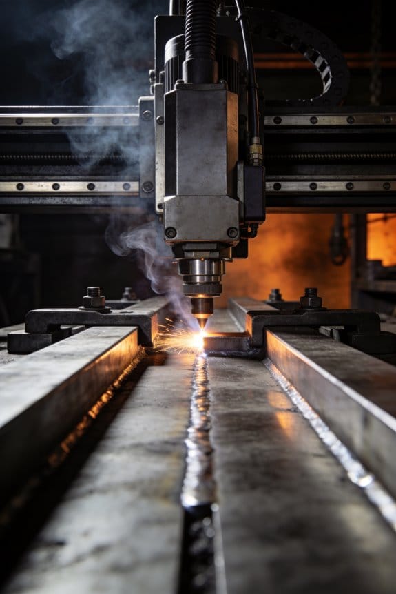
Which Method Is Better for Automated Robotic Welding Cells?
If you’ve ever watched a robot run a welding cell, this is why your choice of process matters: it affects cycle time, part consistency, and maintenance intervals. For most automated robotic welding cells you’ll use MIG (GMAW) because it’s faster, cheaper per part, and simpler to integrate with robot motion and wire-feeding hardware.
Why that matters: faster cycles mean more parts per hour and lower labor cost per part. Example: a small automotive bracket welded with MIG can take 6–10 seconds per part with a single robot, versus 20–40 seconds with TIG.
How to decide between MIG and TIG for your cell:
- Measure your quality need. If you need welds that hold structural loads with standard steel or aluminum, choose MIG. If you’re welding thin stainless or exotic alloys where heat control is crucial, consider TIG.
- Compare cycle time targets. Set a parts-per-hour goal and run a short trial: weld 50 parts and time the average cycle. MIG will usually be 2–4x faster.
- Calculate consumable cost per part. Count wire, shielding gas, and tip wear. Example: mild steel MIG on 0.8 mm wire can cost $0.20–$0.40 per weld; TIG with filler rod and gas often costs more.
- Assess automation complexity. MIG uses continuous wire feed and simpler torch change; TIG needs precise arc starts, filler handling, or a dedicated wire feeder if you want automation.
- Plan maintenance windows. MIG tips and liners are wear items you can replace every few thousand welds. TIG torches require less tip replacement but need more skilled setup.
Practical setup tips you can use:
- Use pulse MIG for thinner material; set peak current 80–120 A for 1.6 mm sheet, pulse background 30–50 A. Try 15–25 Hz pulse frequency.
- Position the robot so the torch lead has gentle bends; keep wire liner runs under 2 meters when possible.
- Program short, consistent dwell points for start/stops to improve repeatability. Record cycle times for 100 parts to spot drift.
Real-world example: a fabricator automated a cell for 2 mm steel brackets. They chose MIG with 0.9 mm ER70S-6 wire, 18 L/min CO2 mix, and hit 9 seconds per part after tuning. Tip changes were scheduled every 6,000 welds and downtime dropped by 40%.
When you should pick TIG:
- You need cosmetic, low-spatter finishes or extremely tight heat input control.
- You’re welding high-value exotic alloys where every weld is inspected visually and repaired if needed.
Example: aerospace fittings in thin titanium often go TIG because the joint tolerances and metallurgy demand it, even though cycle time is slower.
Bottom line: pick MIG for production speed, lower consumable cost, and simpler automation; pick TIG only when the metallurgy or finish requirements force it.
Can TIG or MIG Be Used Safely in Confined or Explosive Atmospheres?
Before you weld in a confined or explosive atmosphere, know why this matters: a small spark can ignite gases or vapors and cause an explosion.
Like walking on thin ice, you should treat TIG and MIG welding in those environments as high risk — avoid them unless you follow strict controls and get specialist approval. For example, at a fuel storage tank repair, teams purge the tank with inert gas and use continuous gas monitors at three heights (0.3 m, 1.0 m, and near the breathing zone) to confirm safe oxygen and flammable limits.
Why you might still do it: sometimes the repair is critical and can’t wait. If that happens, follow these specific steps before you strike an arc:
- Get a written permit from a competent person that lists the hazards and controls.
- Purge the space with inert gas (nitrogen or argon) to below 1% Lower Explosive Limit (LEL) for the target hydrocarbon — measure and record readings every 15 minutes.
- Ventilate to keep oxygen between 19.5% and 23.5% unless you use approved respiratory protection.
- Use intrinsically safe tools and welding equipment rated for explosive atmospheres (look for ATEX/IECEx certification).
- Assign a fire watch who carries a Class B fire extinguisher and stays for 30 minutes after welding stops.
- Continuously monitor for combustible gases with calibrated detectors and log the results.
- Isolate energy sources and lock out/tag out adjacent systems to prevent leaks.
- Use purge dams and inert gas flow rates matched to the vessel size — for example, 10–20 air changes per hour for small tanks, higher for larger volumes.
- Wear appropriate PPE: FR clothing, welding helmet with clear face seal, and supplied-air respirator if oxygen levels are reduced.
A real-world example: a refinery crew needed to plug a leaking nozzle inside a 6 m diameter tank. They shut down product flow, installed inflatable purge dams, flushed the tank with nitrogen until LEL was <0.5%, used ATEX-rated TIG gear, and had two gas monitors and a fire watch on-site; the task took four hours of controlled work.
If you can’t meet every control above, don’t weld. Period. Short sentence.
What to do instead if welding is too risky: remove the part for repair or use cold repair methods. For instance, use a rated mechanical clamp or a non-sparking epoxy designed for hydrocarbon service, applied by a technician who follows the same confined-space procedures.
A final practical tip: train your team on the permit and monitoring process and run a dry rehearsal before any hot work. This reduces surprises and keeps everyone safer.
How Do Maintenance Routines Differ Between TIG and MIG Machines?
The difference between TIG and MIG machines comes down to torch care versus wire care.
Why this matters: keeping the right parts working prevents failed welds and saves you time and money. For example, after a 3-hour TIG session on a stainless hobby project, you’ll often find tungsten discoloration and a clogged gas nozzle.
TIG maintenance: you’ll check the torch and consumables every 2–4 hours of use.
- Clean the tungsten tip every time you stop for more than 10 minutes: grind or re-shape the tip to a 1.5–3.0 mm blunt point for steel, or a sharper 0.5–1.0 mm point for thin aluminum.
- Inspect and replace cups and collets monthly or after 20–40 hours of heavy use; look for cracks or carbon build-up.
- Verify gas flow before each session: set argon to 15–20 CFH (cubic feet per hour) for most TIG steel jobs and 20–25 CFH for aluminum with corners or drafts.
- Calibrate the foot pedal or torch control every 50 hours: run a test weld on scrap, check that amperage changes smoothly between min and max.
Example: on a backyard trailer repair, you’ll swap a scorched collet, re-grind the tungsten to 2 mm, and set argon to 18 CFH to stop porosity.
MIG maintenance: you’ll focus on the wire feed and keep consumables cheap and simple.
- Clean the drive rolls and nozzle weekly, or after every 5–10 kg of wire, removing spatter with a wire brush.
- Check wire tension and alignment before each use: set drive roll pressure so the wire slips with light finger force, not so tight it deforms the wire.
- Replace contact tips after roughly 5–10 hours of heavy welding or when you see arcing marks larger than 1 mm.
- Do a quick calibration of voltage and wire feed speed every 20–40 hours by welding a 50 mm bead on scrap and measuring penetration and bead width.
Example: when fixing a farm gate, you’ll replace a worn contact tip, clean the liner, and run a 50 mm test bead to dial in settings.
Consumables and costs: TIG uses higher-cost consumables per job — tungsten tips, ceramic cups, and higher argon flow — while MIG wire, tips, and gas mixes generally cost less and last longer. For instance, a pack of 10 tungsten electrodes might cost as much as a 5 kg spool of mild steel MIG wire.
Quick checklist before you weld:
- TIG: tungsten shape, cup integrity, gas flow (15–25 CFH), control calibration.
- MIG: clean nozzle and drive rolls, correct drive roll pressure, fresh contact tip, test bead.
Follow these steps, and you’ll spend less time troubleshooting weld defects and more time welding.
Which Welding Method Offers Better Recyclability of Scrap and Waste?
If you’ve ever tossed metal scrap into a bin and wondered what happens next, this matters because recycling choices affect how much of your scrap actually gets reused.
MIG usually gives you better recyclability for scrap and waste because it tolerates mixed metals and makes collection easier. For example: if you’re cutting up an old steel trailer with MIG welds, the welded pieces can often be baled together and sent to a steel recycler without expensive sorting. Steps you can follow:
- Keep welded assemblies grouped by obvious base metal (steel vs. aluminum).
- Remove non-metal attachments like rubber or plastic before sending the load.
- Tell your recycler if the parts were MIG welded so they can expect mixed-but-majority steel material.
TIG, on the other hand, gives you cleaner, purer scrap that recyclers can value higher when the base metal is consistent. This matters because cleaner metal fetches better prices per ton. For example: when you repair a stainless-steel lab bench with TIG, the offcuts are often uncontaminated stainless that a recycler will pay more for. Steps you can follow:
- Separate TIG-cut or TIG-welded offcuts by alloy grade when possible (304 vs. 316 stainless).
- Keep pieces small but free of flux, paint, or other coatings.
- Label batches with the metal type to increase their resale value.
In short, choose MIG if you need forgiving, easy-to-collect scrap handling and quicker recycling; choose TIG when you can keep materials pure and want higher per-ton returns.