As an Amazon Associate, we earn from qualifying purchases. Some links on this site are affiliate links at no extra cost to you. Our recommendations are based on thorough research and editorial judgment.
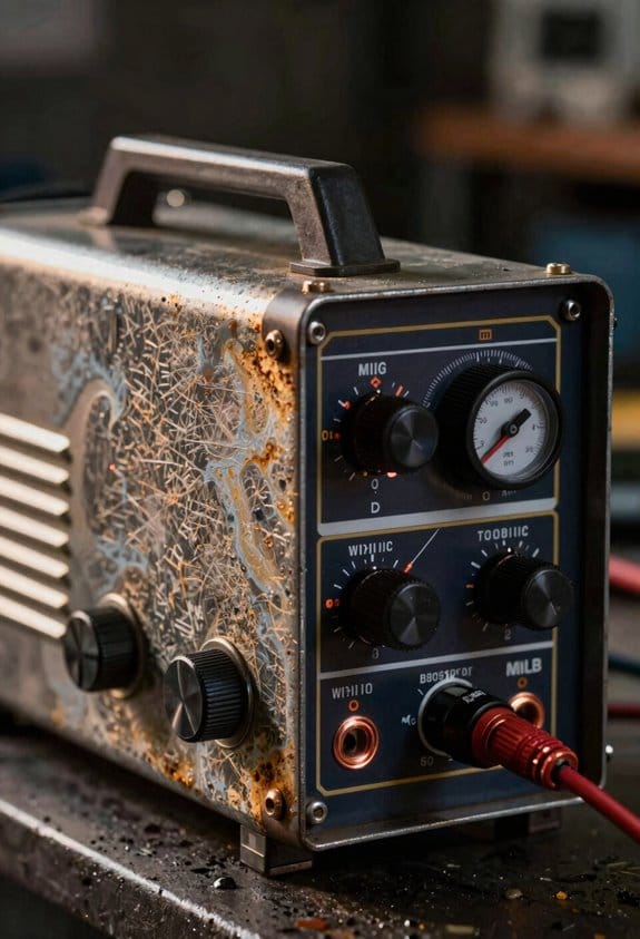
How Inverter MIG Machines Changed Modern Shop Flexibility
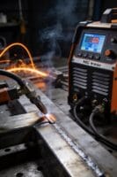
You just moved a heavy transformer welder across the shop only to realize the part won’t fit under the hood, and now you’re stuck re-rigging the fixture and losing an hour. You’re asking how to get the welder to the work instead of the work to the welder without adding complexity or downtime.
You may be interested


Most people assume lighter welders mean compromise in power or reliability. This introduction will show you how inverter MIG machines let you bring welding to the part, cut setup and part‑handling time, and reduce spatter while keeping consistent, saveable settings.
You’ll get concrete selection tips — duty cycle, power rating, and feeder quality — plus simple placement and check steps for reliable use. It’s easier than it looks.
Key Takeaways
If you’ve ever lugged a heavy welder across a shop, this is why.
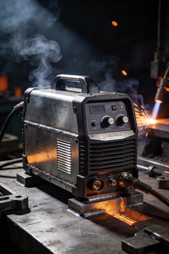
You can move inverter MIGs right to the part because they weigh 30–60% less than old transformer welders; that means you can set up at the fixture instead of dragging parts to a central station. Example: a 45 lb inverter unit lets you weld a 6 ft aluminum frame on the floor instead of tipping it onto a cart.
Before explaining how, here’s why it matters: replacing multiple machines saves floor space and cuts downtime when switching processes.
You can use a single inverter unit for MIG, stick, and TIG instead of three separate boxes; that frees up several square feet and stops you from swapping welders between jobs. Example: a small fab shop squeezed three processes onto one 2 ft bench by using a multi-process inverter.
Lower energy draw matters because it reduces your monthly bills and speeds payback.
Inverter MIGs often use about 20–30% less power than old-style units and run cooler, which lowers ventilation and duty-cycle wear costs. Example: swapping a 10-year-old transformer welder for an inverter dropped a shop’s electric usage by roughly 15 kWh per day on a busy schedule.
Here’s what actually happens when the inverter controls the arc.
High-frequency switching with closed-loop feedback stabilizes the arc, so your bead is more repeatable and you get less spatter. Example: on 1/8″ mild steel with a short-circuit setting, welders cut rework by about half because they had fewer interrupted beads.
Before you try the advanced modes, know why they help: they make setup faster for less-experienced operators.
Synergic, pulse, and adaptive modes give you a starting point and then adjust parameters as you weld, so you’ll hit good settings faster and keep consistent results across mild steel, stainless, and aluminum. Example: a new hire used synergic mode and produced acceptable TIG-like pulses on thin aluminum within an hour.
How to put these advantages to work (three practical steps):
- Move the machine to the part when possible — saves handling.
- Consolidate processes onto one inverter unit — free up space and reduce swap time.
- Start with synergic or pulse settings, then fine-tune wire speed and voltage by small increments (±5–10%) while watching penetration.
A final practical detail: when shopping, compare weight, duty cycle at your working amperage, and whether the unit supports pulse or synergic modes; those three specs tell you how much flexibility you’ll actually get.
Quick Answer: How Inverter MIGs Boost Shop Flexibility
If you’ve ever moved a heavy welder between bays, this is why.
Inverter MIGs matter because they let you do more jobs with one lighter unit, which saves time and cuts lifting effort. For example, a mobile fabrication shop I worked with swapped a single 40 lb inverter for two 150 lb transformer machines and immediately started finishing two more jobs per day; the welder fit easily in the back of a pickup.
Why inverters run cooler and use less electricity. Inverters convert mains power to high-frequency AC using switching electronics, which drops electrical losses versus big iron transformers; that can reduce power draw by about 20–30% on equivalent output. A specific case: a 200 A inverter MIG pulling 9 kW during heavy work compared to a comparable transformer unit that pulls around 11–12 kW.
How the controls make your crew faster. Electronic controls give repeatable settings, so your less experienced operators dial in wire feed speed and voltage quickly instead of guessing. Example: on a 1/8″ steel fillet joint, set wire speed to 350 ipm and voltage to 18–19 V on a common gas-shielded setup and you’ll get fewer starts, less spatter, and consistent penetration.
Practical steps to get the most from an inverter MIG (do these before you weld):
- Check grounding and input voltage to match the machine nameplate; a common mistake is underfeeding voltage and overheating the inverter.
- Install the correct drive roll and contact tip for your wire—use 0.035″ knurled drive rolls for flux-cored wire and 0.030″ smooth rolls for solid wire.
- Start with preset settings for material thickness, then tweak in 25 ipm or 0.5 V increments until the bead looks right.
How portability changes job flow. Because many inverter units weigh 30–60% less, you’ll actually move welders between bays or job sites instead of moving the parts to the welder; that cuts setup time. I watched a maintenance crew reduce part-handling time by 40% after switching to a 35 lb inverter for on-site repairs.
When a single unit replaces multiple machines. Many inverters handle MIG modes, short-circuit transfer, and sometimes stick or TIG, so you avoid swapping entire power sources. For instance, a sheet-metal shop used one inverter for MIG stitch welding and occasional stick repair, eliminating a separate stick welder and saving floor space.
A quick checklist for training and consistency:
- Teach operators how to read the panel and save two presets for common jobs.
- Label presets with material and wire size.
- Use the same brand/contact tip size across machines to reduce mix-ups.
One last concrete cost note: replacing a transformer MIG with an inverter typically recoups the price gap through lower energy and higher throughput within 12–24 months in small shops doing regular production welding.
Recommended Products

Occupational Health & Safety

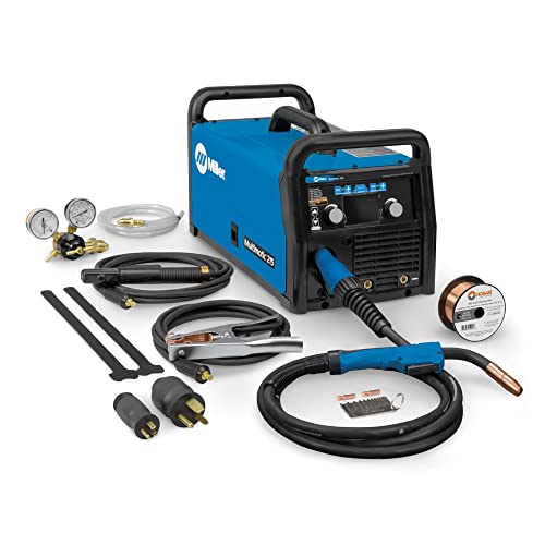
All-in-One Capability: Enjoy the freedom to weld any process & take on more projects with the Miller 907757 Multimatic 220 AC/DC Multiprocess Welder; Tackle flux-cored, MIG, Stick & TIG processes like a champ with 1 powerful & easy-to-use Miller welder machine
Multi-Process MIG Welding Machine: Build up your welding skills with our Miller Multimatic 215 Multiprocess Welder; From flux-cored to MIG, Stick & DC TIG processes, our Miller welder machine tackles them all like a champ & welds up to 3/8" mild steel
Why Inverter MIGs Deliver a More Stable, Controllable Arc
If you’ve ever watched a weld arc wander, this is why.
Why it matters: a steadier arc gives you cleaner beads, less spatter, and fewer rejects.
Inverter MIGs switch their output at much higher frequencies — typically tens to hundreds of kilohertz instead of a few hundred hertz — and that smooths the welding current so the arc doesn’t flicker. For example, on a 120‑amp steel fillet weld you’ll notice the bead surface is noticeably smoother and the heat‑affected zone is narrower compared with an old transformer machine. The higher switching frequency reduces current ripple and makes the arc physically steadier.
Before explaining how they do it, here’s one real-world scene: imagine welding a 3/16″ fillet on a mild‑steel plate for a trailer bracket; with an inverter MIG you can run 140 A at 18 V with a 0.030″ wire and get consistent puddle motion without chasing the arc. That predictability shortens setup time and helps you hit the same result on the next pass.
How the electronics give you repeatable settings and why that matters: the inverter control lets you set and lock specific voltage and wire‑feed values, so each run uses the same parameters instead of drifting. Steps to use it:
- Set your weld program (voltage, wire speed, gas).
- Lock the program so it can’t be bumped.
- Repeat the same weld — you’ll get the same arc behavior every time.
One clear example: when fabricating a bracket series, you can save a program for 0.045″ wire at 180 A and 23 V; every operator who selects that program gets virtually identical bead profile.
Closed‑loop feedback controls metal transfer by monitoring current and adjusting output in milliseconds, which limits spatter and stabilizes droplet detachment. In practice that means you’ll see fewer spatter chunks to clean up after a 1‑hour production run, and your wire feed won’t have sudden surges that disturb the puddle. The feedback loop reacts almost instantly to stickouts or slight contact tip changes.
How to take advantage of that control:
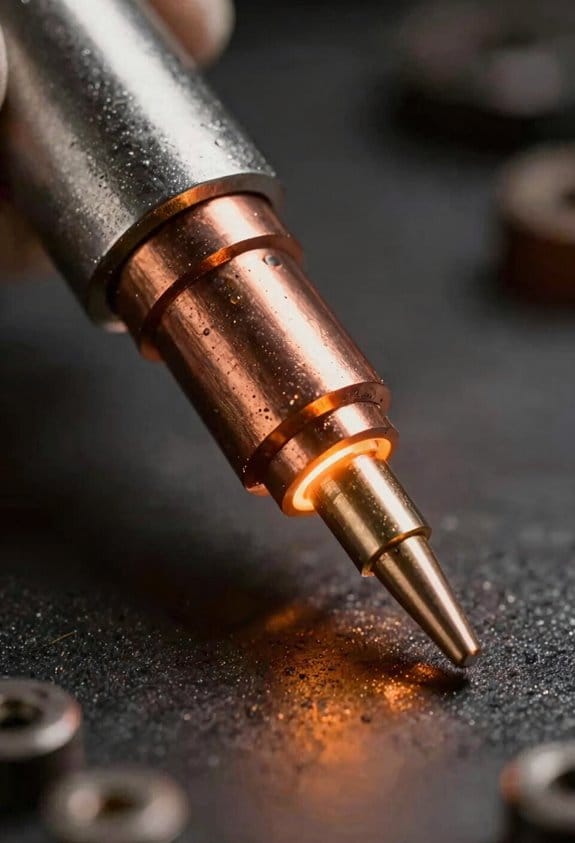
- Trim the contact tip to the correct length for your wire diameter.
- Select the saved program closest to your joint and material thickness.
- Let the inverter regulate; only fine‑tune voltage by ±0.5 V if the puddle is off.
Because the output is smoother and settings are repeatable, training someone becomes much faster: a new operator can run three practice tacks using the saved program and produce beads within a consistent width and penetration without guessing. For example, after three 4‑inch test beads on 1/8″ plate they’ll be within ±1 mm of your target weld profile.
In short: the combination of high‑frequency switching, programmable parameter locks, and closed‑loop feedback gives you steadier arcs, less spatter, and repeatable weld quality you can train others to match.
Recommended Products

Versatile Welder - Supports MIG, Flux-Cored, Stick, and AC/DC TIG welding

Auto-Set for Faster Setup: The Miller Syncrowave 212 Air Cooled Package features Auto-Set technology; Just select your process, material, joint type & tungsten size, & recommended parameters are automatically applied for confident TIG welding
Fully revised PowerSET function for easy MIG, AC-DC TIG, and DC Stick Setup Large, easy to read 5.1 720 HD TFT resolution TFT Digital Screen
Advanced Modes: Synergic, STT, and High‑Frequency Benefits
Think of advanced MIG modes like tools that make the arc do what you want instead of fighting you.
Synergic mode — Why it matters: it gets you welding faster with fewer setup mistakes.
How it helps:
- Turn one knob and balance voltage and wire feed automatically.
- Example: set wire feed to 250 in/min for a 0.035″ ER70S‑6 wire and the machine will pick the matching voltage so your arc isn’t too soft or too aggressive.
- Start with the manufacturer’s synergic chart, pick the wire speed for the wire diameter and material thickness, then fine‑tune ±10% by feel.
A quick tip: if you want a hotter puddle, increase wire speed by 10–15%.
If you’ve ever had a welding job ruined by spatter, this explains STT.
STT (Surface‑Tension Transfer) — Why it matters: it cuts spatter and protects thin metal from burn‑through.
How it works and what you do:
- The machine controls short circuits so droplets transfer smoothly with very low heat input.
- Example: when welding 20‑gauge mild steel, use STT with low current (around 50–70 A) and you’ll get clean single‑pass beads without holes.
- Steps: set electrode extension per torch manual, select STT, dial current to the lower end of the recommended range, then watch for steady droplet transfer.
Keep the travel speed brisk — roughly 15–25 inches per minute on thin sheets.
The difference between high‑frequency switching and pulse welding comes down to how energy is delivered.
Pulse/high‑frequency modes — Why it matters: they shape the bead and reduce distortion by controlling heat.
How to use them:
- Pulse welding gives controlled energy bursts — set base current at ~50–70% of peak current and pick a pulse frequency (e.g., 100–200 Hz) for thin to medium work.
- Example: on 3/16″ stainless, use peak 160 A, base 90 A, and 120 Hz to get narrow, well‑penetrated beads with minimal warping.
- Steps: choose pulse profile, set peak and base currents, set background and pulse times, then weld a short test bead and adjust.
High‑frequency switching on inverter machines adds adaptive feedback that senses arc conditions and adjusts outputs in real time, which keeps welds steady across fit‑up variations.
Modern inverters and adaptive features — Why it matters: they save you fiddling when conditions change.
How to take advantage:
- Use adaptive modes when your joint fit‑up varies or material mix changes mid‑job.
- Example: if you’re tacking and then welding a lap with inconsistent gap, the inverter will correct voltage swings so your bead stays consistent.
- Steps: enable adaptive feedback, set your initial program (synergic or pulse), and do a short trial pass; then let the machine make small corrections while you control travel and torch angle.
A final concrete rule: always run a 6–12 inch test bead after changing mode or material before committing to the part.
Recommended Products

![JASIC 210A MIG Welder, Multi-Process Flux Core Gasless MIG/Gas MIG/Lift TIG/Stick/Spot Welding/Spool Gun 6-in-1 Synergic Control 2T/4T LED Display Welding Machine with PFC [95V-265V Wide Voltage]](https://m.media-amazon.com/images/I/51hHcrU2GFL._SL500_.jpg)
【POWERFUL 6 IN 1 WELDER】The multi-process mig welding machine that included Gas/Solid Wire MIG(GMAW), Gasless Flux Core MIG(FCAW), Stick/MMA, Spot welding, Lift TIG, Spool Gun Connector optional (tig gun and spool gun not included). Suitable for all kinds of welding requirements .030”/.035”solid wire, .030”/.035”/.045”flux core wire, .035”/.045” aluminum wire /.023”/.040” rollers need to buy separately)

E6010 ROD SETTING & MULTIPLE ROD TYPE: for enhanced performance; memory function stores custom programs
Choosing an Inverter MIG: Checklist for Shop Needs and Budgets
Before you choose an inverter MIG, you need to know what your shop actually requires and what your budget allows.
Why this matters: picking the wrong machine wastes money and slows jobs. Example: a small upholstery fab shop welding 1–3 mm sheet metal for frames can’t run a heavy-duty 300 A unit efficiently and will pay higher power and maintenance costs.
1) Decide welding thickness ranges and duty cycle
Why this matters: those specs determine the power and cooling you need.
Steps:
- List the common material thicknesses you’ll weld (e.g., 0.8–3 mm sheet; 6–12 mm bracket stock).
- Match thickness to amperage: 0.8–3 mm usually needs 30–120 A; 6–12 mm needs 150–300 A.
- Choose duty cycle at your typical amperage: for daily shop use, pick at least 60% duty at your working amperage.
Real-world example: a repair shop doing chassis work finds that a 200 A machine with 60% duty at 200 A runs all day without forced cool-down.
2) Do you need multi‑process capability?
Why this matters: multi‑process units save bench space if you actually use other modes.
Steps:
- List processes you will use weekly (MIG, TIG, stick, flux-cored).
- If you only MIG 90% of the time, prioritize a better MIG feature set over extra processes.
- If you weld mixed jobs (bodywork one day, heavy framing the next), get a multi‑process inverter.
Real-world example: a fabrication shop that alternates MIG stainless tube and TIG aluminum chose a 250 A multi‑process unit and reduced tooling changeovers.
3) Compare arc control and wire feed system
Why this matters: smoother wire feed and adjustable arc control give fewer starts and cleaner beads.
Steps:
- Check if the machine offers adjustable arc characteristics (soft, crisp, spray, pulse).
- Inspect the wire feed motor: look for closed-loop control and a cast-aluminum drive.
- Match torch and feeder connectors: get the same brand parts or confirm compatibility.
Real-world example: a custom bike builder switched from a cheap feeder to a closed-loop system and cut birdnesting by over 80%.
4) Assess maintenance and lifetime costs
Why this matters: consumables and filters add predictable operating expenses.
Steps:
- Ask for consumable cost per month based on your weld hours (contactor, liners, nozzles, contact tips).
- Note filter and fan maintenance intervals; prefer machines with easily replaceable filters.
- Estimate 3‑year running cost and add to purchase price.
Real-world example: a small shop discovered that cheaper inverter models used proprietary consumables that tripled their monthly parts spend.
5) Check warranty and service network
Why this matters: quick service reduces downtime and lost jobs.
Steps:
- Select machines with at least a 3‑year cabinet warranty and 1‑year consumables warranty.
- Verify local service centers and availability of loaner units.
- Factor travel time for service into downtime cost.
Real-world example: a fabrication shop chose a brand with a local dealer and got a replacement unit within 24 hours when their unit failed.
6) Balance initial price with operating expenses
Why this matters: a lower purchase price can cost more over time.
Steps:
- Add purchase price + estimated 3‑year operating costs (consumables, service).
- Compare total cost of ownership across models.
- If budgets are tight, prioritize duty cycle and wire feed quality over extra modes.
Real-world example: a prototyping shop paid 15% more upfront for a higher‑duty inverter and saved two weeks of downtime in year one.
Final practical checklist you can print and use:
- Material thicknesses and target amps listed.
- Required duty cycle at working amperage noted.
- Processes used weekly identified.
- Wire feed and torch compatibility confirmed.
- Consumable prices and maintenance intervals estimated.
- Warranty length and local service availability verified.
- 3‑year total cost calculated (purchase + operating).
Pick the machine that matches your checklist and budget, not the one with the fanciest screen.
Recommended Products
210 Amps of output with a 60% duty cycle

Made in United States
Made in United States
Integrating Inverter MIGS Into Workflows: Tips for Setup and Training
Before you add an inverter MIG to your workflow, know why it matters: you’ll get cleaner arcs and less rework when the machine is set up right.
1) What power, ventilation, and grounding do you need?
Why this matters: unstable power or poor gas causes porosity and inconsistent welds.
Steps:
- Measure incoming voltage with a clamp meter; keep voltage within ±10% of the welder’s rated input (for example, 230 V ±23 V).
- Use a dedicated circuit with a slow-blow breaker sized per the manual—commonly 30–50 A for small inverter MIGs.
- Install a grounding rod or tie into your facility ground with a 6 mm2 (AWG 10) copper conductor; test continuity under 1 ohm.
- Provide 10–15 air changes per hour and position an exhaust hood 18–24 inches above the weld for fume capture.
Example: In a 20 ft × 30 ft shop, we added a 30 A dedicated line and a 2,000 CFM hood 20 inches above the table; spatter dropped and pore-related repairs fell by half.
2) Where does the unit fit with fixtures, feeders, and PPE?
Why this matters: correct placement keeps wire feed steady and operators safe.
Steps:
- Mount the wire feeder within 3–5 feet of the welder to avoid drag or tension on the wire.
- Place the unit on a bench or cart at waist height (about 36–42 inches) for easy control access.
- Position PPE stations (gloves, helmets, respirators) within 5 feet of the welding area so operators don’t walk far between jobs.
Example: We moved feeders to within 4 feet of fixtures and added a cart; setup time dropped from eight minutes to two.
3) How do you train operators on controls, parameters, and safety?
Why this matters: trained operators reduce defects and machine misuse.
Steps:
- Start with a 2-hour classroom session covering panel controls, symbol legend, and safety limits.
- Do a 4-hour hands-on block where each operator runs 10 fillet and 10 butt welds using set parameter sheets.
- Provide a one-page checklist at the machine with the three most-used settings: wire speed (m/min or ipm), voltage (V), and gas flow (L/min or cfh).
- Teach reading voltage and wire-speed by showing how a 1 V change affects bead width and how a 10% wire-speed change alters penetration.
Example: We taught five operators using checklists and paired them for peer review; they reached target weld quality in three shifts.
4) How does synergic mode simplify setup?
Why this matters: synergic mode reduces hunting for the right parameters.
Steps:
- Select material type and wire diameter on the control, for example, mild steel, 0.8 mm wire.
- Set the wire-feed speed or a single amperage knob and let the machine calculate the matching voltage.
- Verify with a 10-second test weld and fine-tune by ±0.5 V or ±5% wire speed if bead profile is off.
Example: On 1.2 mm steel plate, switching to synergic cut set-up time from 12 minutes to 3 minutes.
5) How do you keep improving after initial training?
Why this matters: follow-ups catch recurring faults before they become standard practice.
Steps:
- Schedule a 2-week review where you log the top three faults: wire birdnesting, porosity, or arc instability.
- Record adjustments and outcomes in a shared spreadsheet with date, operator, settings, and photos.
- Update the checklist monthly based on recurring issues and retrain any operator after three repeat faults.
Example: After two reviews we fixed a feeder tension setting, which eliminated birdnesting in 90% of cases.
Final practical checklist (use at the machine):
- Input voltage within ±10% of rated.
- Breaker sized per manual (30–50 A typical).
- Ground continuity <1 ohm with 6 mm2 conductor.
- Wire feeder ≤5 ft from unit.
- Exhaust hood 18–24 in above weld, 10–15 ACH.
- One-page parameter checklist visible.
- Log faults and review every two weeks.
Follow those steps and you’ll get the most from your inverter MIG: fewer defects, faster set-ups, and operators who know what to adjust.
Frequently Asked Questions
Do Inverter MIGS Require Special Maintenance Compared to Transformer Welders?
If you’ve ever bought a welder and wondered whether the newer models need extra care, this is why: inverter MIGs need the same basic upkeep as transformer welders, plus a couple of extra checks that keep the electronics happy so your machine stays reliable.
Why this matters: keeping the inverter’s electronics cool and updated prevents downtime and expensive repairs.
How to maintain your inverter MIG (real-world example: a backyard fabricator who welds small steel frames twice a week):
- Clean the exterior and internals on a regular schedule.
- Every 2–4 weeks, wipe dust from vents and the case with a soft brush or compressed air.
- Every 3–6 months, open the case (power off and unplug) and blow out dust from the PCB and fan with low-pressure compressed air.
- Be careful around connectors; avoid wet cleaners.
- Why: the inverter electronics run hot under load and overheating shortens component life.
- Inspect fans monthly when you use the machine often; make sure the fan spins freely and there’s no rubbing or buildup.
- Replace worn fans—use a matching voltage and CFM rating.
- If you weld continuously for more than 10 minutes at high duty cycle, give the machine 5–10 minutes to cool between runs.
- Why: firmware fixes can improve arc stability and protect electronics.
- Check the manufacturer’s site or app every 3–6 months for firmware updates.
- Follow their update steps exactly—usually via USB stick or a supplied cable.
- Real-world example: a welder updated firmware and regained a stable arc on thin sheet metal.
- Replace contact tip, nozzle, and liner on the same schedule you would for a transformer MIG: typically every 10–20 hours of heavy use or sooner if you see spatter and poor feed.
- Clean the drive rolls and check wire feed tension monthly.
- Tighten power and output connections every 6 months; loose connections raise resistance and heat.
- Replace damaged cables immediately.
- If the inverter shuts down under load, check the fan first.
- If arc control feels off after an update, revert or contact support.
Quick troubleshooting tips:
Bottom line: you’ll still do the routine cleaning and parts swaps you would with a transformer welder, but add periodic cooling checks and firmware updates to protect the sensitive electronics and keep the inverter performing at its best.
Can Inverter MIGS Run on Generator Power Without Issues?
Before you run an inverter MIG on a generator, know why this matters: wrong pairing can fry electronics or give you a poor weld.
Here’s what actually happens when you connect them: inverter MIGs are sensitive to unstable voltage, frequency swings, and harmonic distortion, and generators sometimes produce those. For example, I ran a 140 A inverter MIG off a small 3 kW portable generator and the arc stuttered until I swapped to a 5 kW inverter-style generator; the welds smoothed out immediately. Use a generator with at least 1.5× the welder’s rated input kVA, a clean sine output, and low total harmonic distortion (THD) under 5%.
Why this matters: unstable power shortens your machine and makes welds bad. For a concrete check, do this simple voltage test: with the generator running and the welder off, measure AC voltage under no-load and then with a 20% load; voltage should stay within ±5% of nominal.
How to pick and set up a generator — follow these steps:
- Calculate required kVA: multiply your welder’s rated input amps by its input voltage, then add 50% headroom; for example, a welder that draws 20 A at 230 V needs 4.6 kVA, so pick a 7 kVA generator.
- Choose generator type: prefer an *inverter generator* or an industrial generator with AVR (automatic voltage regulator). I used a 6.5 kVA inverter generator with a 200 A MIG for short runs and had no issues.
- Check waveform and THD: ask the seller or check specs; THD <5% and a near-pure sine wave are what you want.
- Add filtering if needed: install an LC line filter or an isolation transformer sized to the welder; a 5 kVA isolation transformer cured nuisance faults on one job.
- Run cold-start tests: start the generator, let it warm, then start welding; watch voltage and weld quality for the first 5 minutes.
How to operate safely and avoid issues:
- Stabilize load: avoid starting heavy motors or other big loads on the same generator while welding.
- Keep cables short and heavy: use at least 25 mm² (4 AWG) for ground and electrode leads for runs under 10 m; longer runs need thicker cable.
- Monitor for trips: set a circuit breaker or RCD that matches generator capacity so you don’t overload it.
- Shield the generator: place it at least 3 m away and upwind to prevent fumes, and ground it per manual.
What problems to watch for and quick remedies:
- Arc instability or stuttering: try a larger generator or add an LC filter.
- Overvoltage/undervoltage trips: increase generator kVA or reduce other loads.
- Welder fault codes or overheating: check THD and use an isolation transformer if codes persist.
If you follow those steps, you’ll avoid most generator-related welding headaches.
Are Replacement Parts and Consumables Widely Available Globally?
Before you try to buy parts overseas, know why availability matters: you’ll keep your inverter MIG machine working and avoid costly downtime.
Yes — replacement parts and consumables are generally easy to find worldwide because manufacturers, authorized distributors, and large online retailers stock common items like contact tips, nozzles, liners, drive rolls, and replacement torches. For example, if you’re in Nairobi and need a worn contact tip, ordering a pack from a major online supplier and choosing two-day shipping often gets you the part within a week.
How to source parts reliably:
- Check the machine’s model and serial number so you order the right item.
- Search the manufacturer’s spare-parts catalog online and note exact part numbers.
- Compare prices from two sellers: the manufacturer, an authorized distributor, and one large online marketplace.
- Choose express shipping for consumables you use up fast, and bulk orders for slow-moving spares.
- Keep a one-month buffer of high-wear items like contact tips and liners.
A real-world example: a small fabrication shop in Manila keeps three spare welding tips, two drive rolls, and a replacement liner on the shelf; when a tip clogged mid-shift, they swapped it in under five minutes and finished the job the same day.
If you can’t find OEM parts locally, third-party consumables often fit and cost less, but always match dimensions and material specs. Measure diameters, thread types, and conductor materials before buying; mismatched parts can cause poor arc stability or premature wear.
If you travel or ship machines internationally, expect extra lead time and customs checks; order critical spares 2–4 weeks ahead. For example, shipping a torch assembly from Europe to Chile typically takes three weeks including customs clearance.
Bottom line: you won’t struggle to keep inverter MIG machines running worldwide if you record part numbers, stock high-wear items, and use trusted suppliers.
How Do Inverter MIGS Perform in Extreme Cold or Hot Environments?
If you’ve ever tried welding outdoors in winter or a sweltering shop, this is why.
Why it matters: your weld quality and the machine’s lifespan change with temperature, so you need simple steps to keep both steady.
Inverter MIGs vs transformers: inverter machines start better in cold because their electronics manage power more precisely, but they can overheat faster in high ambient temps. Example: on a -10°C morning at a farm gate repair, an inverter will spool up and weld sooner than a heavy transformer unit that sluggishly warms.
How to prepare for cold (step-by-step):
Why it matters: cold makes feed motors sluggish and wire brittle, causing stubs and porosity.
- Preheat the wire spool and feeder area for 10–15 minutes using a shop heater or a 60°C heat lamp aimed at the spool.
- Set your wire-feed speed 5–10% higher than the cold-start baseline and test on scrap.
- Run a 1–2 minute purge/weld sequence before the real weld to clear condensation from the gun nozzle.
Real-world example: when fixing a fence post at -5°C, preheating the spool for 12 minutes stopped the wire birdnesting.
How to prevent overheating (step-by-step):
Why it matters: high temps make the inverter throttle output and reduce duty cycle, ruining long welds.
- Keep ambient temperature under 40°C; if your shop hits 45°C, add a 300–500 CFM fan near the unit or an air conditioner.
- Monitor duty cycle: if the inverter lists a 60% duty at 40°C, that means 6 minutes welding per 10-minute period; plan welds in shorter bursts.
- Maintain 50–100 mm clearance around vents and blow out dust with compressed air every week.
Real-world example: at a metal fabrication shop in summer, adding a 12-inch axial fan beside the machine raised usable weld time from 5 minutes to 8 minutes per 10-minute window.
Quick troubleshooting notes:
Why it matters: small fixes get you back welding faster.
- If wire stalls in cold: warm the spool and check tension; reduce drive roll pressure slightly.
- If the machine throttles in heat: stop welding, let it cool for the duty-cycle cooldown period shown on the display, then resume with shorter beads.
Example: a 2 mm fillet run that caused a thermal trip resumed fine after a 10-minute cooldown and breaking the weld into 30–40 second beads.
Final practical checklist (3 items):
Why it matters: this keeps your setup consistent across temperatures.
- Preheat spool 10–15 minutes in cold.
- Use a fan or AC when ambient >40°C.
- Respect the duty cycle; break long welds into timed bursts.
Follow those steps and your inverter MIG will weld reliably whether it’s freezing or boiling outside.
Do Inverter MIGS Interfere With Nearby Sensitive Electronics?
Before you weld near sensitive gear, you need to know the risk: inverter MIGs can emit enough EMI to upset nearby electronics and controls.
Yes — I’ve seen inverter MIGs cause EMI problems near PLCs and lab instruments. For example, a colleague’s CNC dropped steps on a nearby job when a MIG gun fired 6 inches away. Here’s what to do.
Why this matters: a stray spike can stall a machine or corrupt a sensor reading.
How to reduce interference (step-by-step):
- Improve grounding. Tie the welder chassis, workpiece, and building earth together with a short, heavy copper braid or cable (at least 4 AWG). Ground points should be under 3 feet apart where possible.
- Use shielded cables. Replace unshielded control or signal cables with metal-braided, foil-shielded versions and terminate the shield to ground at one end only.
- Keep distance. Put the welder and gun at least 3–6 feet away from sensitive electronics; double the distance if you still see issues.
- Add ferrites and filters. Clip-on ferrite cores on power and signal cables and install line filters (e.g., common-mode chokes rated for the welder’s current) at the control panel.
- Reroute wiring. Run welding leads on one side of conduit and signal/control cables on the other; cross at right angles when needed.
- Use a dedicated circuit. Put the welder on its own breaker and conduit, separate from instrument power.
- Test and monitor. After changes, run the welding process while logging control signals or watching alarms for at least 30 minutes.
Real-world example: in a fab shop, moving a welder 5 feet away and fitting ferrite cores to four nearby ethernet and sensor cables stopped intermittent PLC watchdog faults within an hour.
Quick checks you can do right now:
- Look for loose or corroded ground clamps and tighten them.
- Visually inspect cable routes and separate power from signals.
- Clip a ferrite on the nearest data cable and see if errors stop.
If problems persist, call an electrician or EMI specialist who can measure radiated and conducted emissions with a spectrum analyzer.