As an Amazon Associate, we earn from qualifying purchases. Some links on this site are affiliate links at no extra cost to you. Our recommendations are based on thorough research and editorial judgment.

Why Aluminum Welding Still Drives Interest in TIG Equipment

You’ve just tacked a thin aluminum panel and the bead blows through or the joint warps before you can finish. You’re asking why your welds won’t wet out, why oxidation ruins the puddle, or why cleanup eats up your time. Most people blame filler or amperage without appreciating how heat control and AC cleaning interact on aluminum.
You may be interested


This article shows, step by step, how TIG’s precise heat control and AC cycle remove oxide and prevent burn‑through so your thin or cosmetic parts stay flat and clean.
You’ll learn exact setup, torch handling, and filler feeding that cut spatter and rework. It’s easier than it looks.
Key Takeaways
If you’ve ever tried welding thin aluminum, this is why.
TIG gives you much better heat control, and that matters because too much heat warps thin panels. For example, when you weld a 1 mm aluminum motorcycle fairing, set your amperage around 40–60 A and use a 2–3 mm tungsten to avoid burn‑through; you’ll keep the panel flat. Use short welds (30–50 mm) and let the metal cool for 10–20 seconds between passes.
The difference between clean welds and extra cleanup comes down to how the arc behaves.
TIG tends to produce porosity‑free welds, which saves you time sanding and grinding afterward. Picture a polished aluminum trim piece for a classic car: TIG with 4043 filler and a tight arc makes a shiny bead that needs only light sanding. Use argon at 10–15 L/min and a gas lens to keep contamination out.
Before you try tight, complex joints, you should know why TIG gives control over filler placement.
TIG lets you feed filler wire precisely and steer the arc into corners, so you can weld tight seams and complicated joints with predictable results. For instance, welding a 3 mm aluminum door hinge: rest the torch on the joint, feed 1.6 mm 5356 filler with your other hand, and move 4–6 mm per second for an even bead. Practice that rhythm to avoid underfill.
Think of aluminum oxide like a thin skin that blocks a good weld.
AC TIG provides an oxide‑cleaning action and HF starts that prevent contamination and tungsten inclusions, which matter because oxide traps cause weak spots. On a 2 mm alloy panel, use AC balance around 60–70% cleaning and a frequency of 60–120 Hz to strip oxide while keeping a stable arc. Start with a high‑frequency start or lift‑start technique to avoid tungsten touching the puddle.
If you’re aiming for minimal distortion on thin panels, here’s how skilled TIG operators get predictable results.
Why this matters: less distortion means fewer alignment fixes later. Steps to copy:
- Clamp the panel firmly and use backing bars where possible.
- Set amperage to the lower end for thickness (e.g., 0.8 mm → 30–40 A; 5 mm → 160–200 A).
- Use short stitch welds (30–50 mm) with 10–20 second cool intervals.
- Alternate weld locations to balance heat.
Example: welding an aluminum hood reinforcement strip, clamp every 100 mm and stitch weld in a zigzag pattern; you’ll keep gaps within 0.5 mm.
Final practical tip: if you’re just starting, focus on mastering amp control, short welds, and argon flow — those three adjustments cut distortion and cleanup the most.
Quick Decision: When to Use TIG vs MIG for Aluminum
If you’ve ever tried welding aluminum and ended up with a warped mess, this will help.
Usually, choose TIG when you need precise, clean welds on thin or complex aluminum parts, and MIG when you need faster deposition on thicker sections. Why this matters: the wrong choice means more cleanup, scrapped parts, or a weak joint. Example: welding a 1.5 mm aluminum sheet for a motorcycle fender — use TIG with 1.6–2.4 mm filler rod and 60–90 A for best control.
Before explaining how to pick, here’s the short rule: match thickness, joint type, and finish to the process. Now the how — step-by-step.
1) How to decide by thickness
Why it matters: heat control changes whether the metal warps. Example: a 0.8–2.5 mm boat panel.
- If material is 0.8–3 mm, pick TIG with AC, 50–140 amps depending on thickness, and a 2.4 mm tungsten for steady arcs.
- If material is 3–12 mm, pick MIG (GMAW) with a spool gun, 0.9–1.2 mm wire, and 180–300+ amps for faster deposition.
- For 12 mm and up, consider multi-pass MIG with backing bars. Use shorter arc length. Short arc.
2) How to decide by joint geometry and access
Why it matters: some joints are hard to reach with a big gun. Example: a tight corner on an aluminum bicycle frame.
- For thin, tight, or fillet joints where you need control, use TIG with a small-diameter torch and fingertip control at 10–30 mm/min travel speed.
- For large butt joints or long seams, use MIG with a push angle of 5–15 degrees and a travel speed of 300–900 mm/min depending on wire size.
3) How to think about finish and cleanup
Why it matters: cleanup time eats shop hours and money. Example: a polished aluminum sign.
- If you want minimal spatter and little polishing, use TIG with helium/argon mix (He/Ar 25–75%) for smoother beads.
- If speed and build-up matter more than finish, use MIG with pure argon and prepare for grinding or wire-brushing afterward.
4) How to match shop setup and space
Why it matters: the setup affects throughput and safety. Example: a small garage shop.
- If you have limited space and want faster cycles, a MIG setup with a compact spool gun is easier to store and move.
- If you have fixtures, jigs, and a dedicated welding bench, TIG fits well because it needs room for tooling and careful gas handling.
5) How to match operator skill
Why it matters: the operator determines weld quality. Example: a weekend hobbyist building a trailer.
- If you or your operator is experienced with foot-pedal control and steady hand movement, use TIG.
- If you’re training new staff and need faster results, use MIG with a spool gun and simple preset parameters.
6) Prep steps (do these every time)
Why it matters: aluminum oxide prevents good fusion. Example: a car radiator repair.
- Clean grease with acetone.
- Remove oxide by brushing with a stainless-steel wire brush dedicated to aluminum, or use a grinder with a flap disc.
- Dry parts and clamp to prevent gaps.
- For TIG, purge backside with argon if possible.
Practical settings cheat-sheet (visualize a handheld chart)
- TIG, thin sheet (0.8–2 mm): AC, 50–120 A, 1.6–2.4 mm filler, 1.6–2.4 mm tungsten.
- TIG, medium (2–5 mm): AC, 90–150 A, 2.4–3.2 mm filler.
- MIG spool gun, medium-thick (3–12 mm): DCEN, 0.9–1.2 mm wire, 180–300 A.
- Use argon for MIG shielding; add 25–75% He for higher travel speed and hotter arc.
Final takeaway: pick TIG for thin, detailed work and top-quality finish, pick MIG for faster build-up on thicker sections and higher throughput. Remember to clean oxide, clamp parts, and match amperage to thickness.
Recommended Products

❤️【𝐀𝐝𝐯𝐚𝐧𝐭𝐚𝐠𝐞】Local inventory in the U.S., delivered directly to your doorstep with no extra fees. 10 swing modes, capable of easily handling metal welding below 6mm, with sufficient melting depth and adjustable width; It can efficiently overcome the difficulties of complex joints, curved welds, and large gap processing

【Technical Parameters】Laser Brand: Raycus/MAX; Laser Wavelength: 1080±10nm; Gun Head Model: Relfar; 7 laser welding modes, 10 laser cleaning modes; Welding Width: 0.1-5mm (Continuous/Modulation Dual Modes); Cleaning Scanning Width: 100mm; Cable Length: Standard 10m; Voltage Requirement: 220~242V Single Phase; Cooling System: S&A/Hanli; Cooling Method: Water Cooling; Water Tank Capacity: 16L.

Multiprocess Aluminum TIG Welder: Amp up your welding skills with the Miller 951684 Syncrowave 210 TIG MIG Spoolmate 150 Package; Our multi process welder tackles MIG, Stick & AC/DC TIG processes with just 1 powerful welding machine; Eliminating the need for multiple welders
Why TIG Produces Better Aluminum Welds
If you’ve ever watched a messy aluminum weld fail, this is why.
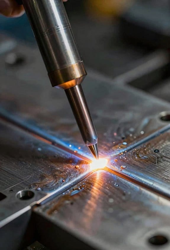
Why it matters: better control means fewer cracks and leaks, and a weld that actually holds under load. Think of TIG as the precision tool for aluminum because it gives you tight control over heat, the arc, and filler metal.
How TIG reduces problems (real-world example): when I welded a 1/8″ 6061 aluminum bike frame tube, I used TIG and avoided burn-through and porosity that showed up when I tried stick welding the same joint. The tungsten electrode is non-consumable, so you manage the arc without adding electrode contaminants that can weaken the joint.
How to set up and weld—step-by-step:
- Clean the metal: wipe with acetone, then use a stainless-steel brush dedicated to aluminum. Example: for a 1/8″ panel, scrub 2–3 passes along the joint until shiny.
- Choose amperage: use about 1 amp per 0.001″ thickness (so 125 amps for 1/8″ aluminum). For thin sheet (≤0.032″), use pulse or lower amps to avoid warping.
- Select filler: ER4043 or ER5356; use ER4043 for general-purpose welds and ER5356 for higher-strength needs.
- Set shielding gas: pure argon at 15–20 CFH for a typical shop torch; use a trailing cup for overhead work.
- Hold a short arc: keep the tungsten ~1/16″ from the work and feed filler into the leading edge of the puddle.
- Control travel speed: move steadily so the puddle stays flat; for a 1/8″ joint, walk the torch at about 3–6 inches per minute.
- Post-weld: let the weld cool in gas for a second, then inspect for porosity or oxidation; grind only if necessary.
Why cleaning and settings matter (visual example): when I prepped a clean 3/16″ sheet before TIG, the bead was shiny and continuous; when I skipped brushing, the weld had pinholes and gray oxide flakes. Adjusting amperage and travel speed to match alloy and thickness gives you predictable mechanical properties and minimal spatter.
A few quick tips you’ll use:
- Use a 2% thoriated or lanthanated tungsten for AC/DC versatility.
- For AC welding of 6061, set balance to favor cleaning—around 60% EN (electrode negative) works well.
- Keep filler rods at hand length so they stay clean; contamination causes porosity.
The result: strong, visually smooth welds with minimal spatter, less post-weld cleanup, and predictable strength—which is why TIG is ideal for high-quality aluminum work.
Why Low Heat Input Matters for Thin Aluminum
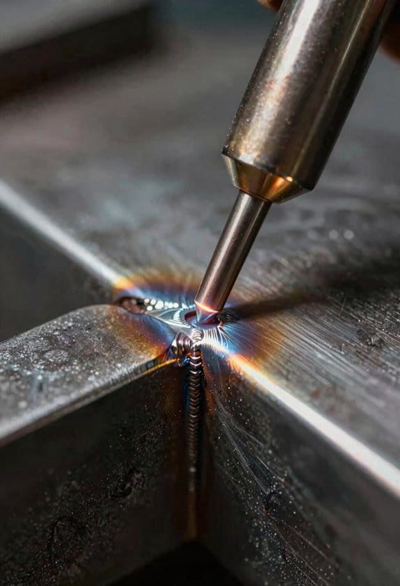
If you’ve ever watched a thin aluminum part warp in seconds, this is why.
Why it matters: Excess heat makes thin aluminum soak up energy and bend, ruining fit and adding hours of grinding and reworking. For example, when you weld a 1/16″ aluminum bracket for a motorcycle fender and run too much amperage, the whole bracket can cup toward the heat and no longer line up with the bolt holes.
How to control heat (the how):
- Set amperage by thickness. Use roughly 1 amp per thousandth of an inch: for 1/16″ (0.062″) start at 62 amps, then reduce by 10–15% if you still see distortion.
- Keep travel speed brisk. Aim for a travel speed of 8–12 inches per minute on 1/16″ material to shorten heat dwell.
- Use shorter arcs and small puddles. Hold a short arc gap — about the diameter of the tungsten — and keep the weld pool under 3/16″ wide on thin sections.
- Try pulsed settings when possible. Set pulse frequency to 1–5 Hz with a background current at 30–40% of peak; this confines the melt and cools between pulses.
- Use tack welds and stitch welds. Tack every 1–2 inches, then stitch 1/2″–1″ welds with 1–2 second gaps to let the part cool.
Real-world tip: When you welded the aluminum license plate bracket on a buddy’s car and it bowed, that was from steady heat and slow travel — switching to 60 amps and stitching fixes it.
Starting and stopping:
- Start gently: use a crater-fill or a short stitch to avoid a hot start that burns through. A 1/4″ starter puddle is plenty on 1/16″.
- End gently: backfill the crater with a short, lower-amperage pulse to prevent a raised, overheated end.
Practice plan (do this on scrap):
- Cut three 3″ x 6″ pieces of the exact same alloy and thickness.
- On the first, vary amperage in 10-amp steps across the length and mark each section.
- On the second, hold amperage constant and vary travel speed.
- On the third, practice short stitches and pulse settings until welds are flat and holes stay round.
Example practice result: With 1/16″ 5052 scrap, you’ll see burn-through at about 80 amps and clean, flat beads at 55–65 amps with 10 ipm travel.
Gear and setup:
- Use a 2% thoriated or ceriated tungsten sized to the amperage (e.g., 1/16″ for 60–120 amps).
- Keep shielding gas at 20–25 CFH and use a #8 cup for visibility and gas coverage.
- Clamp and backstep to a cold metal jig when possible to pull heat away.
One final concrete pointer: if your welds are wide and the part warps, drop your amperage by 10–15% and increase your travel speed by 20% on the next pass.
Preparing Aluminum for TIG: Cleaning and Oxide Removal
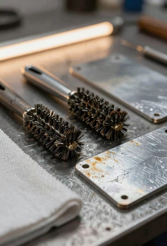
Before you prepare aluminum for TIG welding, know that the oxide layer melts at a much higher temperature than the base metal, so if you leave it you’ll get poor fusion and porosity.
1) Remove oils and grease (why this matters: grease burns and creates inclusions). Example: wipe a 6×6 inch plate with a lint-free rag soaked in acetone for 10–15 seconds per pass until the rag comes away clean.
Steps:
- Put on gloves and work in a ventilated area.
- Saturate a clean, lint-free cloth with acetone or methyl ethyl ketone (MEK).
- Wipe the part in straight strokes; change cloth when it looks dirty.
You’ll stop organic contamination that spoils the weld.
If you’ve ever watched oxide form instantly, this is why a mechanical scrub matters. Use a stainless-steel brush dedicated to aluminum to knock off the hard oxide without embedding iron.
Steps:
- Use a new or dedicated stainless brush (crimped stainless, not carbon) and keep it for aluminum only.
- Brush along the joint for 20–30 seconds with medium pressure until the surface looks bright.
- Replace the brush when bristles bend or show rust.
Real example: on a 1/8-inch aluminum sheet lap joint, a 30-second scrub along the seam left a clean, bright 1/2-inch band for reliable TIG starts.
Before you tackle tight joints, know chemical methods remove oxide where brushes can’t reach and they neutralize faster than you might expect. For crevices use a mild acid dip like a 5% nitric acid solution or a proprietary aluminum etch for 30–60 seconds, then rinse thoroughly with clean water for at least 60 seconds.
Steps:
- Mix a 5% nitric acid bath (50 mL acid per 950 mL water) in a plastic container — always add acid to water.
- Submerge the part for 30–60 seconds, agitate gently.
- Rinse immediately under running water for 60 seconds and dry with clean compressed air or a lint-free cloth.
Example: a 3-inch tube-to-plate joint cleaned this way allowed full-penetration TIG beads without signs of oxide entrapment.
Final cleaning before welding matters because oxide reforms quickly; you’ll get the best results if you remove it right before you strike an arc. Right before welding, give the joint one last pass with a fresh stainless brush or a non-scratch abrasive pad (scotch-brite green), then start welding within 30–60 seconds.
Steps:
- Use a fresh brush or pad and go over the weld area for 10–20 seconds.
- If you used solvents or water rinse, dry completely — use filtered compressed air if possible.
- Begin welding within 30–60 seconds of the final clean to minimize re-oxidation.
Real example: on a 1/4-inch aluminum plate, starting the TIG bead within 45 seconds of the final brush pass produced a smooth, shiny weld with minimal porosity.
Safety and tool notes: wear gloves and eye protection when using solvents and acids, and always ventilate the area. Use only stainless tools marked for aluminum to avoid iron contamination; a tiny amount of iron can cause big weld problems.
How TIG Achieves Superior Weld Quality on Aluminum
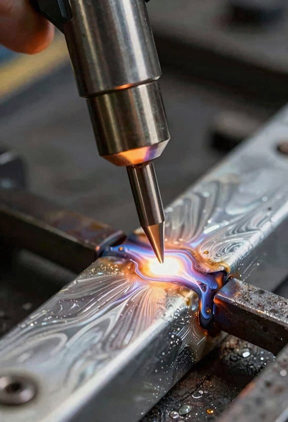
Here’s what actually happens when you TIG weld aluminum: it gives you tight control over heat and cleanliness, and that directly affects strength.
Why this matters: controlling heat and contamination keeps the joint ductile and predictable. For example, when you TIG weld a 3 mm 6061-T6 aluminum bike frame tube, precise heat limits distortion so the tube stays round and the joint holds weight without cracking.
How you control heat (short list of steps):
- Set your AC frequency to 60–100 Hz and balance to 30–40% electrode positive for a focused arc on 3–6 mm material.
- Use a low amperage ramp at the start—about 60–80% of your target for 0.5–1 second—to wet the joint, then jump to full amperage.
- Keep travel speed steady: ~10–15 mm/s on 3 mm sheet, slower on thicker parts.
Steps make the grain finer, which increases strength.
Why cleanup matters: oxide on aluminum melts at ~2050°C while the base metal melts at ~660°C, so any oxide stops the weld from fusing properly. For example, if you wipe a 5 mm 6063 panel with solvent and then wire-brush it with a stainless brush, you’ll avoid pinholes and silver streaks in the weld.
How you clean and prepare:
- Degrease with acetone, then wire-brush perpendicular to the joint using a dedicated stainless brush.
- Remove the last 1–2 mm of oxidized edge on older parts before tacking.
This keeps contaminants out of the pool.
How filler choice affects the result:
- Match filler to the base alloy when possible—use ER4043 for 6xxx series to reduce cracking, ER5356 for strength on 5xxx series.
- Use a 1.6–2.4 mm filler rod for most manual welds on 2–6 mm material.
Matching alloy avoids brittle intermetallics and keeps ductility.
Technique tips that give you consistent appearance and strength:
- Use a 2–3 mm tungsten for 3–6 mm work and sharpen to a 20–25° point for AC.
- Maintain a 2–3 mm arc length and a 70–80° torch angle for fillets.
- Feed filler into the leading edge of the puddle, not the arc.
These habits make beads look uniform and reduce defects.
How to avoid common defects:
- For porosity: purge with argon at 8–15 L/min, and ensure joint fit is <0.5 mm gap for thin panels.
- For burn-through: reduce amperage by 10–20% and increase travel speed, or backstep welds on thin areas.
- For lack of fusion: increase heat slightly or clean the edge better.
Fixes are usually simple adjustments, not new equipment.
Quick real-world checklist before you weld:
- Clean with solvent, wire-brush, and remove 1–2 mm oxide.
- Set AC 60–100 Hz, balance 30–40% EP, and preflow argon 1–2 seconds.
- Use correct filler and tungsten size, and tack every 25–50 mm on thin sections.
Follow this and your joints will have predictable properties and good looks.
TIG Features That Improve Aluminum Welding (Pulse, HF Start)
If you’ve ever watched aluminum warp or burn through, this is why.
Pulse welding: why it matters in one sentence — it controls heat so you don’t melt your joint or leave cold spots. I use pulse modulation to alternate high and low current so you can control heat input and reduce distortion on thin aluminum; set your peak current to about 100–130% of the steady-state amperage and your background to 20–40% for 1/8″ (3 mm) plate. Example: when I welded a 3 mm aluminum bracket, I used 120 A peak, 35 A background, 2 ms pulse width at 2–4 Hz to get a smooth, even bead without burn-through. Steps to set pulse for a new joint:
- Measure base current for continuous weld (amperage that makes a good puddle).
- Set peak to 100–130% of that and background to 20–40%.
- Start at 1–4 Hz frequency and 30–50% duty cycle, then adjust to shape the puddle.
HF arc start: why it matters in one sentence — it starts the arc without touching the tungsten so your electrode and weld stay clean. HF ignition gives you a non-contact arc start that prevents tungsten contamination and keeps the weld zone pristine; for example, when I tig-welded an aluminum muffler flange, using HF start avoided tungsten pits that would later cause porosity. How to use HF start:
- Set your torch trigger to “HF” or “lift + HF” on the machine.
- Bring the torch within about 2–6 mm of the joint and press the trigger to initiate the arc without touching.
- If the arc fails to start, increase HF output or move slightly closer, then retry.
Together they make welding aluminum more consistent and reduce defects. Using pulse for heat control and HF for clean starts gives you a stable arc, less distortion, and fewer tungsten or porosity problems.
Recommended Products

【POWERFUL 7-IN-1 TIG WELDER AC/DC】The Welder is capable of welding with DC HF TIG / DC Pulse TIG / DC SPOT TIG / AC HF TIG / AC Pulse TIG / AC SPOT TIG / STICK Welding Methods. AC TIG is used in finesse welding various aluminum alloys, magnesium alloys, and other non-ferrous metals. DC TIG provides low-temperature control. You need precise welding for various types of steel: stainless steel, carbon steel, aluminum-magnesium alloy.

Offers standard type pulse feature for AC and DC, and a special Advanced Pulse for AC for welding thin material, increasing travel speed and reduces warping. Can be used with optional finger amp control torch.
Choosing TIG Equipment for Aluminum: Inverters, Cooling, Portability
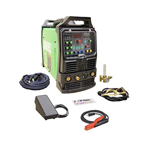
If you’ve ever hauled a welder to a job and cursed the weight, this is why inverter TIGs matter: they give you precise control, save energy, and are actually portable enough to carry between sites. You want an inverter when you’re welding aluminum sheet or small parts because it makes a stable arc and lets you dial in current in single-amp steps; for example, a 200 A inverter that can run down to 5 A will let you weld 1–3 mm sheet without burning through. Check the machine’s rated lifespan (usually given in hours) and look for units with active cooling because long duty cycles push heat into the electronics.
Before you pick cooling, know why it affects uptime: heat shortens electronics life and raises maintenance needs. For a visual: imagine welding a 2 mm aluminum panel for an hour at 120 A; a fan-only unit may need a 15–30 minute cooldown cycle, while a liquid-cooled torch can keep going with only brief pauses. Choose reliable fans if you do light-to-moderate work — for example, a unit with a brushless fan and replaceable filter — and choose liquid cooling for continuous high-amperage jobs, like TIGing 6 mm plate at 180–200 A for extended periods, because liquid systems run cooler and quieter.
Before you buy a portable powerpack, understand why matching matters: mismatched weight or output makes transport harder and performance worse. Step 1: weigh your travel case and welder together so you don’t end up with a 40 kg setup you can’t lift. Step 2: choose a powerpack that provides at least 20% more peak current than your maximum welding amperage to avoid voltage sag on starts. For instance, pair a 160 A inverter with a 200 A-capable powerpack if your site power is marginal.
Why input power and duty cycle matter: they determine how long you can weld and how often you must stop. Example: a 230 V single-phase inverter rated 35% duty at 150 A lets you weld for 3.5 minutes in every 10; that fits small repairs but not continuous fabrication. Check these three specs before buying:
- Input voltage and phase (e.g., 115/230 V single-phase or 400 V three-phase).
- Duty cycle at the amperage you plan to run (look at % at 60% of max current).
- Cooling type and service interval (fan filter change or coolant replacement interval in months).
Why this reduces downtime: matching duty cycle and cooling to your job keeps you welding instead of fixing gear. Practical example: a mobile fabber replaced a fan-only unit with a liquid-cooled inverter and went from 20-minute waits every hour to continuous welding with only 30-minute maintenance per week.
Recommended Products

Auto-Set for Faster Setup: The Miller Syncrowave 212 Air Cooled Package features Auto-Set technology; Just select your process, material, joint type & tungsten size, & recommended parameters are automatically applied for confident TIG welding

Heavy-Duty IGBT Power Modules increase reliability and performance
210 Amps of output with a 60% duty cycle
Common Aluminum TIG Challenges and Practical Fixes
If you’ve ever watched a puddle of aluminum go bad, this is why.
Oxide: why it matters — oxide raises aluminum’s melting point and prevents a good weld. Example: on a 1/8″ 6061 bike frame tube, a thin gray film can keep the weld bead from wetting the parent metal. How to fix it:
- Clean with acetone or alkaline cleaner and wipe with a lint‑free cloth.
- Scrub the joint with a dedicated stainless wire brush and always brush in the weld direction.
- If you’re welding right after cleaning, use a fresh brush and keep the area under argon for 5–10 seconds before striking.
- For heavy oxide, sand with 120–220 grit and then re‑clean.
Tip: hold the torch at a 10–15° trailing angle and use a 100% argon flow of 15–20 CFH for small TIG torches.
Porosity: why it matters — trapped gas creates weak, pitted welds that leak and look bad. Example: porosity appeared when joining two thin 5052 plates with a gap, leaving pinholes across the bead. How to fix it:
- Dry parts in an oven at 150°F (65°C) for 30 minutes if they’ve been exposed to moisture or cutting fluid.
- Fit joints to leave ≤0.020″ gap on thin sheets; clamp to eliminate air pockets.
- Set shielding gas to 12–25 CFH depending on torch size and wind conditions. Increase flow by 5 CFH in drafts.
- Use filler that matches the base alloy; mismatched filler can trap hydrogen.
Short test beads eliminate guesswork.
Burn‑through: why it matters — too much heat melts holes in thin material and ruins the part. Example: while trying to fill a lap joint on .028″ foil, the puddle punched through within seconds. How to fix it:
- Lower amperage: for .028″ use 20–40 A; for 1/16″ use 40–80 A.
- Use pulse: 50–200 Hz with a 30–60% duty cycle helps control heat input on thin sheets.
- Pick a smaller tungsten (1/16″ or 1/32″) and a short arc length (~1/16″).
- Use backing bars, chill blocks, or tack welds every 1–2″ to carry away heat.
Practice a short bead on scrap before starting.
Tungsten contamination: why it matters — a contaminated tungsten ruins arc stability and puts tungsten into your weld metal. Example: I watched a 3/32″ thoriated tungsten get speared into a puddle when the arc wandered, leaving a black dot in a 1/4″ aluminum plate. How to fix it:
- Start on a scrap piece or use lift TIG start; don’t dip tungsten into the puddle.
- Grind the tungsten to a 20–30° point for DC and 30–45° for AC; run it clean and replace if you see a rounded, discolored tip.
- Keep tungsten diameter matched to amperage: 1/16″ up to 100 A, 3/32″ up to 200 A.
- If contamination happens, stop, grind off 1/8″ of the tip, and start again.
Edge cracking: why it matters — cracks start where heat and alloy mismatch create stress, causing parts to fail later. Example: welding a 1/4″ 7075 gusset to a heat‑treated part produced a hairline crack at the toe after cooling. How to fix it:
- Use filler with higher ductility when joining heat‑treatable alloys (e.g., 4043 for 6061 in many cases).
- Reduce heat input: lower amperage, faster travel speed, or pulse settings (see burn‑through numbers).
- Preheat only when recommended for the alloy — for thicker 2xxx and 7xxx series, follow manufacturer guidance.
- Maintain an even bead width and avoid heavy reinforcement at the toe.
Use a test coupon to confirm your filler and heat strategy.
Keep a small notebook by your machine with these reference numbers: argon 12–25 CFH, thin sheet amperage ranges (20–80 A), tungsten sizes matched to ampere limits, and oven‑dry times (150°F / 65°C for 30 minutes).
Recommended Products

True All-Process - excellent performance on MIG, Flux-Cored, STICK (including 6010 electrodes), DC TIG and AC TIG industrial applications

Product Type: Electronic Component

TIG Welding And Accessories
Aluminum TIG Use Cases: Automotive, Aerospace, Precision Fabrication
If you’ve ever tried welding thin aluminum and watched it warp, this is why.
Why it matters: controlling heat keeps thin panels flat and seams strong. In automotive work you’ll use TIG when you need precision on body panels and lightweight brackets that must fit tight tolerances.
Example: repairing a thin 1.2 mm door skin on a classic car. Use 60–90 A on a TIG machine with a 1.6 mm (1/16″) 2% thoriated or lanthanated tungsten, a 1.6–2.4 mm filler rod (ER4043), 20–30 psi of pure argon, and 2–3 mm arc length. Clean the joint with a stainless brush and acetone, hold a 60° angle, and make short 2–4 second weld passes to avoid burn-through.
Before you weld aerospace components, you need to know how traceability and low-defect counts change your setup.
Why it matters: aerospace parts require documented parameters and fewer defects. Use TIG on thin sections or complex fittings where porosity and inclusions are unacceptable.
Example: joining a 2.5 mm 6061-T6 gusset for a light aircraft. Record amperage (80–100 A), gas flow (20–25 psi), travel speed (7–12 mm/s), filler alloy, and preheat (if specified). Use back-purging when welding thin sections that form oxides on the inside surface.
Think of precision fabrication like working on a mechanical watch; tiny errors ruin the fit.
Why it matters: delicate assemblies need consistent seams so parts assemble without shimming. TIG gives you the fine control to build small fixtures, jigs, and custom brackets with repeatable results.
Example: making a 0.8 mm aluminum bracket for an optical mount. Set 30–50 A, a 1.0–1.6 mm filler, and short, controlled puddles; clamp the bracket to prevent distortion and allow a 30–60 second cooling interval between passes.
Practical prep steps before any aluminum TIG job:
- Clean parts: remove grease with acetone, then mechanically remove oxide with a stainless wire brush dedicated to aluminum.
- Fit and clamp: ensure a uniform gap (0.5–1.5 mm for thin sections).
- Choose tungsten: use 1.6 mm 2% lanthanated for general work; sharpen to a 30–45° point for DCEN.
- Set shielding: pure argon at 15–30 psi, cup size matched to the weld (sized so gas covers the arc and 10–15 mm beyond).
- Pick amperage: match to thickness—about 15–20 A per 0.1 mm of material for thin sections.
Why technique matters: steady hands and consistent travel avoid burn-through and porosity. Keep a short arc, pause between short welds on thin pieces, and use stitch welding to distribute heat.
Example: stitch-welding a 1.5 mm seam—run 3–5 mm welds spaced 10–15 mm apart, then fill gaps after parts stabilize.
Final quick tips:
- Use filler rods matched to alloy (ER4043 for 6xxx series, ER5356 for 5xxx) for strength and corrosion needs.
- Avoid contaminated filler—store rods in a dry container.
- Document parameters when traceability is required: amperage, travel speed, gas flow, tungsten size, filler alloy, and joint prep.
If you follow these specific settings and steps, you’ll control distortion and make clean, durable aluminum TIG welds.
Costs, Productivity, and Future Trends in Aluminum TIG Adoption
If you’ve ever watched a shop struggle with warped aluminum parts, this is why.
Why it matters: switching to TIG for aluminum can cut scrap, rework, and cleanup time so your jobs finish faster and cost less.
TIG costs versus savings
Why it matters: you need to know where your money goes so you can plan payback.
1) Upfront equipment: expect $2,000–$6,000 for a good inverter TIG machine with AC capability for aluminum, plus $200–$500 for a water-cooled torch if you weld a lot. Buy a proven brand and get a 3–5 year parts warranty.
2) Training: budget 20–40 hours per operator for basic aluminum TIG skill, roughly two to five supervised jobs to gain consistency.
3) Maintenance: plan $150–$300 per year for consumables and inspection if you keep a simple checklist.
Example: a small shop bought a $3,500 TIG unit and trained one welder for 30 hours; within three months they cut scrap by 15% and recovered the training and part of the machine cost.
How TIG reduces material and labor costs
Why it matters: fewer mistakes and less finishing save real dollars.
1) Reduce scrap: TIG’s precise heat control reduces burn-through and distortion; expect scrap reduction of 10–25% on thin panels.
2) Cut cleanup time: less spatter means you’ll spend 30–60 minutes less per assembly on grinding and sanding.
3) Lower replacement parts: accurate welds mean fewer remakes and fewer lost deadlines.
Example: on 1 mm aluminum panels, switching to TIG dropped replacement cycle time from 4 hours to 2.5 hours per panel, and saved about $8 per panel in labor and material.
Productivity trade-offs and training plan
Why it matters: you’ll be more productive only if operators are trained correctly.
Steps:
1) Start with a 4-hour classroom on AC balance, pulse, and filler rod technique.
2) Do 16 hours of bench practice on 1.5 mm, 2 mm, and 3 mm samples using lap, butt, and fillet joints.
3) Complete five real-part welds under a mentor, with feedback and measured distortion checks.
4) Track performance for 90 days and adjust torch settings by +/−10% based on results.
Example: a welder who followed this plan went from inconsistent bead width to repeatable 3–4 mm beads and cut rework time by half.
Future trends that affect your ROI
Why it matters: picking the right features now helps you avoid premature upgrades.
- Inverter efficiency: newer inverters save energy and give more stable arc; expect 10–20% lower power draw versus older rigs.
- Pulse controls: pulse gives you better puddle control on thin stock and reduces heat input; use pulse when welding under 2 mm.
- IoT monitoring: basic telemetry can flag consumable wear and reduce unscheduled downtime by tracking hours.
Example: a shop that added IoT logging to two TIG stations caught a failing water pump early and avoided a week of downtime.
Planning checklist before you adopt TIG
Why it matters: concrete prep makes adoption smoother and faster.
1) Choose machine: pick AC inverter with 200–300 A peak for flexibility.
2) Schedule training: set aside 40 hours per new operator.
3) Prepare consumables: stock collets, cups, tungsten types (2% thoriated or ceriated for AC), and filler rods.
4) Set metrics: track scrap rate, rework hours, and average weld time weekly.
Example: using that checklist, one shop rolled out two TIG stations in six weeks and saw measurable savings by month three.
Bottom line: plan the purchase, train to a standard, and measure the results; with that approach, TIG for aluminum usually pays back through less scrap, less finishing, and steadier schedules.
Recommended Products

Standard features include: high frequency start, lift arc tig start, automatic downslope, pulse, repeat (latch) function, memory function and automatic gas management
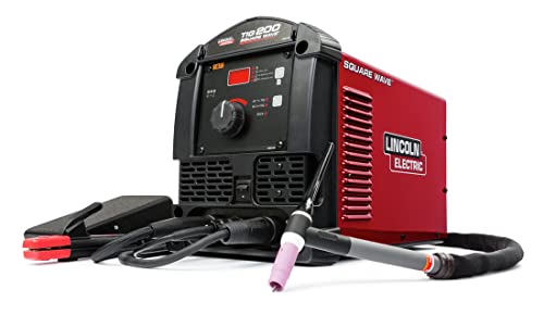
The user interface makes machine setup easy. Available features, such as Pulse, which provides a drumbeat-like rhythm for filler metal deposition, make you become a better TIG welder - faster.

All-in-One Capability: Enjoy the freedom to weld any process & take on more projects with the Miller 907757 Multimatic 220 AC/DC Multiprocess Welder; Tackle flux-cored, MIG, Stick & TIG processes like a champ with 1 powerful & easy-to-use Miller welder machine
Frequently Asked Questions
Can TIG Welds on Aluminum Be Reliably Inspected Nondestructively?
Before you inspect TIG welds on aluminum, know why it matters: missed internal porosity or cracks can cause sudden failures under load.
Yes — you can reliably NDT TIG aluminum welds if you follow a clear, repeatable process. I’ll show you specific checks and tools so you can do it yourself.
Section 1: What surface defects can you find visually?
Why it matters: surface issues are the easiest to catch and often indicate deeper problems.
Example: on a 3 mm aluminum boat hull panel, a row of small pinholes along the weld bead usually means gas entrapment during welding.
1) Clean the weld with acetone and lint-free cloth.
2) Use a 10x loupe or magnifying lamp and good daylight or a 5,000 K LED light.
3) Look for porosity, lack of fusion, undercut, and irregular bead shape.
If you see pinholes or undercut, mark them with a grease pencil and measure their length with a tape; note that any continuous crack over 2 mm needs further testing.
One quick fact: visual inspection with 10x magnification will catch surface porosity down to about 0.2 mm.
Section 2: How do you use dye penetrant testing (PT) for aluminum?
Why it matters: PT finds surface-breaking cracks that visual checks can miss.
Example: testing a welded RV frame joint revealed a 1.5 mm hairline crack only after penetrant — it was invisible under oil and grease.
Steps:
1) Degrease with solvent, rinse, and dry.
2) Apply visible red penetrant and let dwell 10–30 minutes.
3) Remove excess with a water-based cleaner; dry again.
4) Apply developer (dry powder or non-aqueous) and wait 10 minutes.
5) Inspect under white light; any red lines show cracks.
If you find indications, measure length and photograph with a scale; repeat PT after any repair.
Section 3: When should you choose ultrasonic testing (UT)?
Why it matters: UT locates internal porosity, lack of fusion, and volumetric flaws you can’t see.
Example: a 10 mm thick marine bulkhead had clusters of internal porosity 4–6 mm deep that caused reduced fatigue life, found only by UT.
Steps:
1) Use a 5–10 MHz straight-beam probe for plates 3–25 mm thick; use a wedge or angled probe for weld toes.
2) Couple with ultrasound gel and scan in 5–10 mm passes along the weld.
3) Use A-scan and B-scan to size indications; calibrate on a known reference block first.
4) Record depth and length of any indications; anything larger than 3 mm in critical structures needs evaluation.
UT takes practice; run a few known samples until your amplitude and time-of-flight readings match expected values.
Section 4: When is X‑ray (radiography) the right choice?
Why it matters: radiography shows internal cavities and density changes with a picture you can archive.
Example: an aircraft alloy spar had a subsurface gas pocket 12 mm long that only appeared on a radiograph and led to a repair before fatigue testing.
Steps:
1) Choose film or digital radiography based on access and cost.
2) Position source and detector so the X-ray beam is perpendicular to the weld centerline.
3) Use exposure settings suited to alloy and thickness (for 6 mm 6061-T6, start around 40–60 kV with appropriate mAs; adjust based on film density).
4) Develop or process the image and interpret dark spots as possible porosity and lighter streaks as lack of fusion.
Keep radiation safety procedures and qualified personnel in place.
Section 5: How do you combine methods for repeatable confidence?
Why it matters: no single NDT method finds every flaw; combining methods reduces risk.
Example: on a pressure vessel lid, I ran visual, PT, UT, and finally radiography on suspect zones and avoided an expensive in-service failure.
Steps:
1) Start with visual and PT for surface issues.
2) Use UT for internal volumetric scanning of the whole weld.
3) Reserve radiography for verification of critical indications or when UT access is limited.
4) Document all findings: photos, scan maps, sizes, and calibration records.
A combined approach finds surface and internal defects and gives you a reproducible inspection record.
Final practical tips:
- Always clean aluminum welds before any test; grease masks defects.
- Keep inspection records for at least two years or per your spec.
- If you’re unsure about an indication larger than 3–5 mm in a critical part, consult a certified NDT Level II or III.
Do this, and you’ll get reliable, repeatable NDT results on TIG aluminum welds.
How Does Aluminum Filler Selection Affect Corrosion Resistance?
If you’ve ever picked a filler rod and later seen pits or streaks on the weld, this is why. Corrosion matters because it shortens your part’s life and can cause leaks or failures.
Filler chemistry steers how the weld microstructure changes during cooling, so choose a filler that matches your base alloy’s composition within a few tenths of a percent for best results. Example: when welding 6061-T6 sheet, use a 4043 or 5356 filler per the weld procedure; 4043 reduces hot cracking and gives better resistance in most atmospheres, while 5356 can be stronger but may corrode faster in saltwater.
Filler selection also limits intergranular corrosion by avoiding elements that form continuous anodic films at grain boundaries; pick fillers with lower silicon and controlled magnesium for heat-treatable alloys. For instance, marine fittings made from 6061 alloy welded with 5356 filler will show more galvanic activity at the bead than those welded with 4043.
Finally, filler choice guarantees galvanic compatibility with the base metal if you match or make the weld slightly more noble than the surrounding alloy; that prevents a sacrificial bead. Example: when joining pure aluminum to 3003 sheet, choosing a filler like 4043 keeps the joint from acting as a strong anode in a humid environment.
Quick steps you can follow:
- Identify the base alloy and temper.
- Check manufacturer or code tables for recommended fillers (e.g., AWS A5.10).
- Pick the filler that matches composition within ~0.2–0.5% for critical parts.
- Test a sample weld in the expected environment (salt spray for marine use).
If you do those, you’ll avoid most corrosion surprises.
Is Post-Weld Heat Treatment Ever Required for Aluminum TIG Joints?
Before you weld age‑hardening aluminum, know whether heat treatment can restore strength — that decides if you need post‑weld work. Example: a 6061-T6 bicycle frame welded with TIG will lose most of its T6 strength in the weld and HAZ unless you treat it afterward.
If your alloy is age‑hardening (like 2xxx, 6xxx, 7xxx series), then yes — you may need solution heat treatment, rapid quench, and then natural or artificial aging to get strength back. Why this matters: without it your joint can be as much as 50% weaker than the parent metal. Real example: a welded 6061-T6 bike tube that’s solution heat treated at ~530°C (985°F) for one hour per inch of thickness, water‑quenched, then aged at 160–177°C (320–350°F) for 8–12 hours will regain much of its original strength.
How to do it in steps:
- Identify alloy and temper. Use the stamp or supplier data. Example: 6061-T6 stamped on the tube.
- Solution treat at the specified temperature (e.g., ~530°C for 6061) for the recommended time — typically one hour per inch of thickness.
- Quench rapidly in water immediately after solution treat.
- Age naturally at room temperature for several days (T4 → T6) or perform artificial aging at ~160–177°C for 8–12 hours to reach the desired temper.
If your alloy is non‑heat‑treatable (like 1xxx, 3xxx, 5xxx series), post‑weld aging won’t help; instead, consider mechanical stress relief or redesigning the joint. Why this matters: you’ll waste time and risk distortion if you try heat treatment on these alloys. Example: a 5052 sheet panel welded by TIG should be stress relieved by stretching or low‑temperature baking rather than solution treating.
A few practical cautions:
- Use calibrated thermocouples or a furnace with good controls; +/-10°C matters for final properties.
- Expect distortion during solution heat treatment; clamp or fixture your parts if alignment matters.
- If you can’t perform shop‑scale heat treatment, consider using filler and technique that minimize softening, or choose a different alloy.
If you want, tell me your alloy and part dimensions and I’ll suggest specific temperatures and times.
What PPE Is Specifically Recommended for Aluminum TIG Welding Fumes?
Before you start TIG welding aluminum, you need to know why PPE matters: the fumes can irritate your lungs and long-term exposure can harm your nervous system.
You should wear a respirator rated for fine particulates and metal fumes. Use a P100 (NIOSH-rated) cartridge respirator for best protection; an N95 is a minimum for short jobs but won’t filter oil-based mists as well. Example: for a 2-hour sheet-aluminum weld with poor ventilation, wear a P100 half-mask with P100 cartridges.
Use local fume extraction to keep the air clear. Why this matters: capturing fumes at the torch cuts your airborne exposure by most of the plume. Step 1: position a portable fume extractor nozzle 2–6 inches from the weld. Step 2: run it at the manufacturer’s recommended flow (often 100–200 CFM for near-field capture). Example: a small shop uses a 150 CFM unit with a 4-inch nozzle and reduces visible smoke at the weld.
Protect your skin and clothing from sparks and UV. You’ll want flame-resistant clothing — cotton or rated FR shirts and pants work; avoid synthetics. Example: wear a gray cotton long-sleeve shirt and leather welding jacket for a 1–3 hour TIG session.
Use the right helmet and eye protection to block UV and bright arc glare. Pick a TIG helmet with a variable shade 8–13; set shade 10 for 150–200 amps, shade 8–9 for below 100 amps. Always wear safety glasses under the helmet for side protection.
Wear welding gloves that balance dexterity and heat protection. Choose TIG-specific leather gloves (goat or cowhide) with a 6–8 inch cuff for hand mobility and wrist protection. Example: use size-specific TIG gloves when doing 1–5 mm root passes on thin aluminum.
Quick checklist you can follow before welding:
- Put on P100 half-mask or P100 disposable respirator.
- Turn on and position local fume extractor 2–6 inches from the joint at 100–200 CFM.
- Wear cotton or FR long sleeves and leather jacket.
- Don TIG leather gloves and helmet set to the correct shade.
- Wear safety glasses under the helmet.
That’s the practical kit: a P100 respirator, local fume extraction, FR/cotton clothing, TIG gloves, a variable-shade TIG helmet, and safety glasses.
Can Robotic TIG Systems Match Manual Welder Aesthetics on Aluminum?
Think of robotic TIG welding like a camera on a steady tripod.
Why it matters: you’ll get consistent bead shape and heat control across long runs, which reduces rework. I once watched a robotic cell lay 200 linear inches of 1/8″ 6061-T6 butt joints with identical ripples; each pass used the same 90–100 A, 3/32″ tungsten, and 15–18 scfh argon flow.
Robotic systems can match — and sometimes beat — your aesthetics when you set them up right.
How it works: the robot repeats exactly the same torch angle, travel speed, and wire feed (if using filler), so consistency replaces fatigue. Example: on a stack of three identical aluminum brackets, the robot produced welds that required only light sanding before anodizing, while my hand welds on the fourth bracket needed two passes.
If you want similar results, do these steps:
- Program the robot for the joint geometry and set travel speed to 6–12 ipm for common 1/8″ to 1/4″ aluminum welds.
- Use a short arc length (about 1.5–2.0 mm) and keep tungsten size at 3/32″ for that amperage range.
- Teach the torch angle at 10°–15° push for TIG on aluminum and set pulse (if available) to 50–75 Hz with 30–40% background current for a nice ripple.
- Run one sample bead, measure penetration and bead width, then adjust amperage by ±5–10% as needed.
A practical note: you still need a skilled operator to set parameters and inspect parts. For example, on a 1/4″ 5052 panel I supervised, the robot produced perfect beads but we had to tweak heat control after two trial runs to prevent slight burn-through at corners.
Short sentence for emphasis.