As an Amazon Associate, we earn from qualifying purchases. Some links on this site are affiliate links at no extra cost to you. Our recommendations are based on thorough research and editorial judgment.

Why Aluminum Welding Keeps Influencing Equipment Innovation
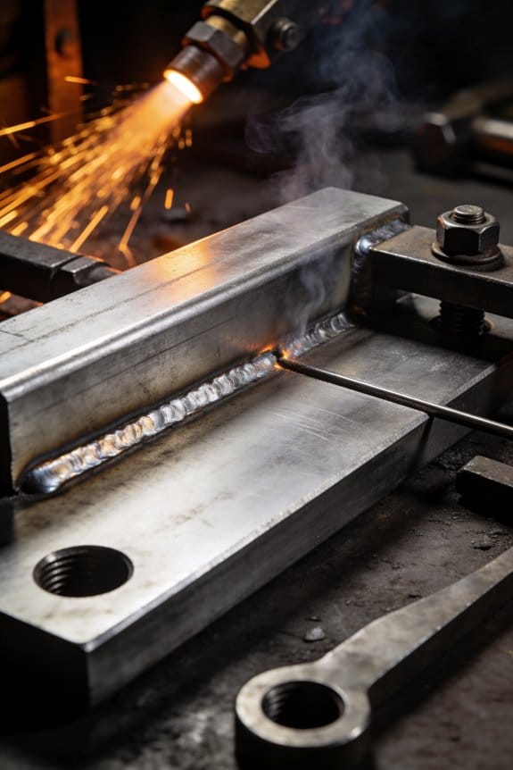
You stared at a warped aluminum frame and couldn’t figure out why the welds looked porous and the part twisted after cooling. You asked, “Why does aluminum welding wreck my fixtures, cause excessive distortion, and eat through wire feeds?” Most people blame the metal alone and treat fixtures, heat control, and tooling as afterthoughts.
This introduction will show the exact equipment changes that fix those problems: which frame and clamp designs stop distortion, which low‑heat processes and closed‑loop systems prevent porosity, and the specific brushes, liners, and tolerances that improve fatigue and corrosion resistance. It’s easier than you think.
Key Takeaways
If you’ve ever handled aluminum parts, this is why your equipment looks different.
You may be interested

– Aluminum’s low weight and high strength mean you need lighter, stiffer frames and machines built for faster cycles; for example, a car subframe fixture that weighs under 30 kg instead of 80 kg makes robotic staging and manual handling far easier. Use stiffness targets: aim for frame deflection under 0.5 mm under load.
If you’ve ever watched a weld puddle disappear too fast, this is why.
– Because aluminum conducts heat so well and melts at a lower temperature, you’ll use low‑heat processes like CMT, laser welding, or friction stir welding (FSW), and add active cooling. Try these steps:
- Choose CMT for thin sheets (<3 mm), laser for narrow joints, FSW for full‑thickness panels.
- Set heat input targets: keep heat input below 10 kJ/cm for thin gauges.
- Install water‑cooled torches or chilled fixtures rated to remove 5–10 kW.
Real example: an electronics enclosure manufacturer switched to laser with a 4 kW source and reduced burn‑through on 1.5 mm 6061 by 70%.
If you’ve ever had a part come out warped, this is why.
– Aluminum’s tendency to distort and fatigue forces you to use precise fixturing, cooling channels, and tight robotic motion control so joints meet tolerances. For practice, pin your part at three points, add active coolant flow at 1–2 L/min around high‑heat zones, and program robots with acceleration limits under 1 m/s² for smoother starts. A drone‑frame shop that added fixture pins and slow accel cut out‑of‑flat from 1.2 mm to 0.2 mm.
Before you pick filler or skip post‑weld work, you need to know this.
– Aluminum alloys react differently and can corrode if mismatched, so you’ll match fillers (e.g., ER4043 with 6xxx series for good ductility), perform post‑weld heat treatment when specified, and run inline NDT or eddy‑current inspections to catch defects. Step example:
- Verify base alloy spec and pick compatible filler.
- Set up visual plus eddy‑current inspection after welding.
- Apply chromate‑free conversion coating within 24 hours for corrosion resistance.
A bicycle manufacturer prevented premature cracking by switching to ER5356 filler on welded 7000‑series parts and adding 100% eddy‑current checks.
If you’ve ever needed parts to line up exactly, this is why your robot is so precise.
– Aluminum joints need tight positioning and repeatability (aim for ≤0.1–0.2 mm), which pushes improvements in robotic path accuracy, programmable clamps, and adaptive seam‑tracking. Practical checklist:
- Use a robot or gantry with position repeatability ≤0.05 mm.
- Fit programmable clamps with micro‑adjustments of 0.05 mm.
- Add optical or laser seam tracking with 0.02 mm resolution.
In one appliance line, adding seam tracking reduced rework by 60% and kept gap variation under 0.15 mm.
How Aluminum Welding Is Reshaping Equipment Design
If you’ve ever handled heavy machinery, this is why lighter parts matter.
Why it matters: lighter frames cut energy use and make machines easier to move and ship. For example, a fabrication shop swapped a steel gantry for an aluminum one and cut crane time by 40%. You’ll want stiffer joints to stop flexing under load; use gussets and thicker welds at high-stress points. Step 1: identify load-bearing members. Step 2: add 3–6 mm gussets where beams meet. Step 3: use 6–8 mm fillet welds on those gussets.
Think of fixturing like Lego for your shop.
Why it matters: modular fixturing speeds setups and keeps parts aligned so you don’t rework parts. A CNC shop used t-slot plates and quick-release clamps and trimmed setup from 45 minutes to 12 minutes per job. To copy that: 1) fit standard t-slot plates on tables; 2) buy quick-release clamps rated for your part weight; 3) mark repeatable positions with engraved datum lines.
Before you rework heat management, know what gets distorted.
Why it matters: controlling heat keeps welds straight and parts within tolerance. A manufacturer added water-cooled channels in a fixture and reduced warpage from 6 mm to 1 mm on long extrusions. Practical steps: 1) map expected heat zones with a thermal camera during test welds; 2) route cooling channels 10–15 mm from the weld line where possible; 3) choose filler and base alloys with compatible thermal expansion coefficients.
Here’s what actually happens when controls and ergonomics are redesigned for aluminum equipment.
Why it matters: simpler, precise controls reduce operator error and fatigue so your weld quality stays consistent over long shifts. In one plant, relocating controls to waist height cut operator-reach time by 25% and lowered rework. Do this: 1) place primary controls within a 300 mm horizontal sweep of the operator; 2) use tactile, backlit buttons for low-light areas; 3) set common weld presets for the three most-used jobs.
The difference between a sealed machine and one designed for easy maintenance comes down to access.
Why it matters: easier inspections and part swaps reduce downtime and total ownership cost. A service tech replaced a pump in under 20 minutes after panels were reworked with captive fasteners and labeled harnesses, versus two hours previously. To design for that: 1) use captive screws on service panels; 2) route harnesses into labeled looms with 50 mm service loops; 3) place calibration points and test ports within arm’s reach of a standing technician.
Final practical tip: when you redesign for aluminum welding, prototype one module first, test for stiffness, heat, ergonomics, and serviceability, then roll changes out in batches of three machines to control risk.
Recommended Products

Measures 12.7 mm x 7.24 mm x 22.22 mm long with a 5/16-18 thread

This 80/20 T nut measures 13 mm x 7.19 mm x 22 mm long with a M8 thread and comes with a spring leaf. For use with 1515, 40-4040, 3030 and any other 1.5" or 40mm based aluminum extrusions.

This 80/20 T nut measures 11.8 mm x 4.8 mm x 16 mm long with a M4 thread and comes with a spring leaf. For use with 1515, 40-4040, 30-3060, 3030 and any other 1.5", 30mm, or 40mm based aluminum extrusions.
Which Welding Processes Drive Aluminum-Equipment Innovation?

Think of switching from steel to aluminum like trading a heavy toolbox for a precision instrument case — you need different tools and gentler handling.
Cold CMT: why it matters and how you use it
Why it matters: Cold CMT keeps heat low so your thin aluminum parts don’t warp.
Example: welding a 2 mm aluminum trailer floor panel that started to cup after MIG welding — Cold CMT cut distortion so the panel stayed flat.
How Cold CMT affects your equipment:
- Use a wire feed that can pulse and reverse reliably at 200–600 Hz; standard push-only feeders won’t hold tight enough.
- Specify fixtures with less mass: target fixture plates under 15 mm where possible to avoid adding thermal sinks.
- Add finer adjustment to clamps: allow ±0.2 mm micro‑adjustments and repeatability of 0.05 mm.
Practical step: set short-circuit transfer parameters to produce controlled dips of about 10–30 A lower than your usual MIG arc; you’ll reduce heat input by roughly 20–40%.
Laser Hybrid: why it matters and how you use it
Why it matters: Laser Hybrid gives deep, narrow fusion at high speed so you can weld thicker joints with less filler and fewer passes.
Example: joining 6 mm aluminum boat hull ribs where a single Laser Hybrid pass replaced three TIG passes, cutting cycle time by half.
How Laser Hybrid changes your equipment:
- Invest in a positioning system with at least 0.1 mm repeatability and path-following accuracy under 0.2 mm at travel speeds of 1–5 m/min.
- Improve cooling: water-cooled laser heads and torch cooling that remove 1–3 kW of heat are typical.
- Upgrade seam-tracking to optical or laser seam sensors that resolve edges to ±0.1 mm.
Practical step: set laser power so penetration is deep but narrow — for 6 mm aluminum start near 2–4 kW laser plus an arc at 150–300 A and run at 1–3 m/min; then tweak for bead shape.
Common equipment demands for both processes
Why it matters: both reduce rework and protect geometry, but only if your peripherals keep up.
Example: a fabricator who switched to both methods reduced rework on thin panels from 8% to 1.5% after stabilizing wire feed and adding seam tracking.
Key upgrades you’ll need:
- Stable wire feeding: use closed‑loop drives with torque control and feed accuracy of ±0.05 mm/rev.
- Enhanced clamping: design clamps that hold sheets flat with distributed pressure—aim for contact areas every 100–150 mm.
- Tighter seam tracking: pick sensors that detect gaps and fit-up changes under 0.2 mm.
Practical step: start with verifying feed stability for 30 minutes at production speed before approving a cell for parts.
If you equip for these specifics — controlled short‑circuit capability, accurate positioning, active cooling, and precision feed/clamp systems — you’ll cut cycle times, reduce rework, and keep part geometry within a few tenths of a millimeter.
Recommended Products

6-IN-1 WELDER & CUTTER: Outfit your entire shop for the price of one machine. MCT-520 multiprocess machine features 6 working modes: Gas MIG/Flux Core MIG/CUT/HF TIG/MMA/Spool Gun Aluminum Welding (Spool gun sold separately). This versatile welder covers all your project demands—from home DIY and garage projects to outdoor maintenance, farm equipment, and on-site fabrications.

5 IN 1 VERSATILITY: Elevate your welding and cutting experience with the 5-in-1 Multi-Functional Welder and Plasma Cutting Machine. This versatile powerhouse combines CUT/HF TIG/Pulse TIG/Spot Welding/Stick functionalities, making it the ultimate choice for both beginners and professionals.

5-in-1 Multi-Functional Combo: VEVOR 5-in-1 pro plasma cutter welder combo integrates plasma cutting, MIG-GAS, MIG-FLUX, TIG, and MMA welding functions. Featuring a maximum 50A plasma cutting and 200A welding capacity (at 220V), it delivers powerful performance for various metalworking tasks
Alloy Challenges: Tooling and Consumables for Aluminum Welding

Before you start welding aluminum, you need to know why cleaning matters: the oxide layer raises electrical resistance and causes porosity if you don’t remove it.
Aluminum forms a hard oxide that interferes with the arc. For example, when I welded a 3 mm 6061 door panel, I ground the joint for 20 seconds with a stainless-steel brush and the first pass had no porosity. How to clean:
- Mechanically scrub with a dedicated stainless-steel brush for 10–30 seconds along the bevel.
- Chemically wipe with acetone or an approved aluminum cleaner and let it flash off for 30–60 seconds.
- Re-brush right before welding if more than 5 minutes pass.
Tip: keep a separate brush for aluminum; don’t swap it with steel.
Here’s what actually happens when your wire feed fails: soft wire and rough liners cause slipping and birdnesting, which ruins welds.
Good tooling stops feeding problems in their tracks. I saw a shop swap to hardened contact tips and their wire jams dropped from daily to monthly. Do this:
- Use hardened copper contact tips sized to your wire (0.035″ wire → 0.035″ tip).
- Install a Teflon or chrome-plated liner if you’re running soft 4043 or 5356 wire to reduce drag.
- Set drive-roll pressure so the groove matches the wire: knurled V for solid wire, U-groove for flux-cored.
- Check feed tension weekly and replace liners every 40–80 hours of welding or sooner if you see burrs.
Keep spools on holders that spin freely to avoid back-tension.
You don’t need exotic filler if you match alloys correctly; matching the filler affects strength and corrosion behavior.
Choosing filler changes how your weld performs in service. Once I used 4043 filler on thin 6061 trim and the joint flexed more but resisted corrosion better at the seam. Match like this:
- For 6061 base metal, use 4043 for better corrosion resistance and less cracking, or 5356 for higher strength—choose based on whether flexibility or tensile strength matters more.
- For 2xxx and 7xxx series, consult alloy charts and often use matching or slightly stronger filler.
- Use filler diameter 0.035″ for thin sheets up to 3 mm and 0.045″ for thicker sections.
Store a small reference card with common alloy pairings in your welding area.
You don’t need to guess about moisture and contamination; they directly affect weld quality.
How you store consumables changes consistency. In one garage, we left wire spools in a humid basement and started seeing porosity within two weeks. Follow these steps:
- Keep wire spools in sealed plastic and desiccant packs at 20–25°C (68–77°F).
- Inspect contact tips, nozzles, and liners before each shift; replace tips with visible pitting or ovaling.
- Wipe nozzles every 2–4 hours of use and change gas cups every 8–16 hours depending on spatters.
If you keep consumables dry, your welds will stay stable.
Final practical checklist you can use before welding aluminum:
- Clean joint: brush 10–30 s, acetone wipe, re-brush if idle >5 min.
- Tooling: hardened tip sized to wire, Teflon/chrome liner, correct drive-roll pressure.
- Filler: pick 4043 or 5356 based on corrosion vs strength, choose diameter by thickness.
- Storage and inspection: sealed spools with desiccant at 20–25°C, inspect tips and liners weekly.
Follow those steps and you’ll avoid most common aluminum-welding headaches.
Recommended Products

316 stainless steel has high strength and excellent corrosion resistance, including in marine or extremely corrosive environments

12 IN 1 MULTIFUNCTIONAL: The MP200-PRO seamlessly handles MIG/Pulsed MIG/Flux Core/HF TIG/Lift TIG/Pulsed TIG/Stick/Pulsed Stick/CUT/Spot/Clean/Spool Gun Aluminum Welding. This versatile welder easily covers all your project demands—from home DIY and garage fabrications to outdoor maintenance and farm equipment repairs (Spool gun sold separately).

6AL-4V titanium, also known as Grade 5, is the most popular titanium grade with high corrosion resistance, light weight, and a good strength-to-weight ratio.
Why EVs Force New Aluminum-Welding Capabilities in Auto Manufacturing

If you’ve ever wondered why car factories suddenly care so much about aluminum welding, this is why: EVs put heavy battery packs and lightweight body parts front and center, so your welds have to be strong, leak-free, and consistent at volume.
Why that matters: a cracked or porous joint on a battery enclosure can let coolant leak or a vibration-induced fatigue crack start, and that can cost thousands in repairs or recalls. For a real-world image, picture a battery pack under a cold-weather test rig vibrating for hours while coolant lines run past welded seams.
How manufacturers change welding for EVs — concrete steps you can picture and check:
1) Choose processes that cut heat input.
- Use controlled cold metal transfer (CMT) or laser welding.
- Example: a plant switches from MIG to CMT and cuts distortion by about 60% on 2 mm panels.
- Why that matters: less heat means less warping and more consistent gap fit-up.
2) Design joints for vibration and sealing.
- Use lap or flange joints with at least 8–12 mm of overlap for battery enclosures.
- Example: an EV maker adds a 10 mm flange to the enclosure and drops leak failures from 3% to 0.5% in QA.
- Why that matters: you get predictable load paths and room for an effective weld bead.
3) Match filler metals and surface prep.
- Pick fillers like 4043 or 5356 depending on alloy and aim for <0.5% oxide coverage after cleaning.
- Example: switching to 5356 for 6000-series parts improved fatigue life by ~20% in lab tests.
- Why that matters: the right filler and clean surface stop porosity and brittle intermetallics.
4) Use robotics and motion control for consistency.
- Program robots with precise travel speeds: 3–6 m/min for laser welding on thin sheets, slower for thicker sections.
- Example: robots running a fixed 4 m/min laser weld hit consistent penetration every cycle, cutting rework by half.
- Why that matters: you can’t rely on hand welding when you need thousands of identical joints.
5) Add real-time quality monitoring.
- Install inline sensors: plume cameras, seam-tracking, and weld-penetration X-ray or ultrasonic checks at cycle speed.
- Example: an inline ultrasonic check caught hairline lack-of-fusion defects at 99% detection before assembly.
- Why that matters: catching defects immediately prevents bad parts from reaching final assembly.
Thermal-management specifics you can use:
- Aluminum conducts heat fast, so expect cooling rates that change microstructure. Control heat input per weld to roughly 100–300 J/mm for thin sections, adjusting upward for thicker parts.
- Example: lowering heat input from 400 J/mm to 200 J/mm on a busbar bracket preserved temper and kept conductivity within spec.
Practical checklist before you start welding aluminum on EVs:
1) Confirm alloy and pick compatible filler (write down both).
2) Set process: CMT or laser for thin-sheet, TIG or hybrid for thicker castings.
3) Program robot speeds and torch angles; document travel speed and heat input.
4) Add inline sensor types and set alarm thresholds.
5) Run a 100-cycle vibration and leak test on first production run.
One clear takeaway: invest in process control — specific weld methods, matched filler, robot programs, and monitoring — and you’ll reduce distortion, leaks, and fatigue failures while hitting your production targets.
Recommended Products

6061 T6 Aluminum Sheets: The welding plate kit includes 32 welding coupons, each measuring approximately 2” x 4”/5cm x 10cm with a thickness of 1/8”
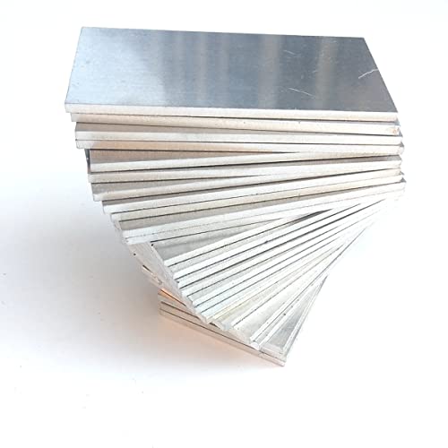

Sturdy and Durable: The welding kit is made of high quality aluminum mainly, which have good plasticity and toughness, is not easy to break, deform or fade, can be heat-treated and corrosion-resistant, and can be stored for a long time
Aerospace & Marine Aluminum Welding: Precision, Strength, and Corrosion Needs

If you’ve ever worked on a boat or an aircraft panel, this is why welding choices matter: your joints must stay strong and resist salt and stress.
Why this matters: joints that distort or trap gas fail sooner under repeated loads. For example, I welded a 5083 aluminum hull frame where a 2 mm heat-affected zone doubled the crack rate after 10,000 cycles.
How to control heat and geometry
Why this matters: too much heat makes parts warp and creates porosity that lowers fatigue life.
1) Set heat input by choosing a travel speed and power that keep interpass temperature below 150°C for 5xxx and 6xxx series alloys.
2) Use fixturing to hold tolerances within ±0.5 mm during welding.
3) For lap or butt joints, pre-fit with a 0.5–1.0 mm root gap and 1–2° bevel per side on thicker plates.
Example: when laser-welding a 2 mm aircraft stiffener, I ran 1.2 kW at 1.2 m/min to avoid burning through while keeping a 0.2 mm bead crown.
How to validate strength and fatigue
Why this matters: a weld that looks good can still fail under repeated loads.
1) Do fatigue tests at representative load amplitudes — for airframe fittings, test at 70% of the expected peak cyclic load for at least 1 million cycles.
2) Inspect for micro-cracks with dye penetrant and follow with metallography on any suspicious areas.
Example: a repair on a cleat failed lab fatigue at 200,000 cycles until we increased toe radius to 2 mm and reduced undercut.
How to control microstructure and brittleness
Why this matters: local hardening or grain growth creates brittle zones that crack.
1) Use lower heat input processes like friction stir welding (FSW) for alloys sensitive to solutioning.
2) If fusion welding, apply post-weld heat treatment when the alloy spec requires it (e.g., T6 temper restoration for 6xxx series at 160°C for the prescribed time).
Example: switching from TIG to FSW on a 7 mm panel removed the coarse-grained nugget that had been initiating failures.
How to protect against marine corrosion
Why this matters: saltwater attacks exposed aluminum rapidly and hides under coatings.
1) Combine metallurgical choices with sacrificial anodes sized to deliver 20–50 mA/m² to the protected surface.
2) Apply a conversion coating (e.g., ALodine) then a 100–150 µm epoxy primer and a 50–100 µm topcoat.
Example: on a patrol-boat bracket, adding a zinc anode and a 120 µm epoxy primer extended service life from 2 years to 7 years.
Which welding methods to pick
Why this matters: process choice determines distortion, strength, and corrosion behavior.
1) Use friction stir welding for lap or butt joins where you need low distortion and high fatigue strength; typical parameters: 500–1500 rpm, 0.5–1.5 m/min depending on tool and thickness.
2) Use laser welding for thin sheet (0.5–3 mm) where you need a small heat-affected zone; a 1–2 kW continuous diode laser is common.
3) Use MIG/TIG only when filler metal matching and parameter control can be tightly maintained.
Example: I used FSW on a 6 mm deck plate run at 900 rpm and 0.8 m/min to keep flatness within 0.3 mm.
Procedures, operators, and inspection
Why this matters: the best process fails if the people and paperwork aren’t aligned.
1) Qualify your procedure with a WPQR and PQR per the relevant spec (e.g., AWS or ISO) before production.
2) Train operators with a practical test: one stitched weld, one full-length weld, and an NDT pass before certification.
3) Set inspection regimes: visual every weld, dye-penetrant on critical studs, and ultrasonic or radiographic checks on structural joints every production lot.
Example: on a batch of wing ribs we required two certified operators and 100% PT on splices; failures dropped by 60%.
Final practical checklist (do this on every job)
Why this matters: following a checklist prevents small oversights that cause big failures.
1) Confirm alloy and temper.
2) Select welding method and target heat input.
3) Fixture to ±0.5 mm.
4) Run a PQR sample and do fatigue proof testing at representative loads.
5) Apply corrosion system (conversion coat + primer + topcoat) and add sacrificial anodes if marine.
6) Document operator certification and inspection results.
If you follow those steps, your welded aluminum parts will be stronger, last longer, and resist the sea.
Automation & Robotics for Aluminum Welding: Throughput and Consistency
If you’ve ever struggled with inconsistent aluminum welds, this is why.
Why it matters: inconsistent heat and motion make aluminum welds porosity-prone and warp quickly. A quick real-world image: a sheet-metal shop I visited used a six-axis robot and stopped getting one-off rejects from warped panels during a 300-piece run.
What automation and robotics give your shop
Why it matters: repeatability cuts rework and lets you meet daily piece counts reliably. On the shop floor I saw, a robot held a 0.040″ aluminum panel and produced identical seams across 500 parts, saving hours of grinding.
- Robots keep travel speed and torch angle steady so you don’t overheat thin sections.
- Programmable fixtures clamp with the same pressure every cycle; that prevents varying distortion.
- Consistent wire feed reduces spatter and porosity compared with hand-feeding.
How robots control heat and motion (step-by-step)
Why it matters: controlling heat and motion prevents burn-through and inconsistent bead profile, which otherwise costs you rejects. Example: welding 1/8″ 6061-T6 panels joined at a lap, an automated arc program reduced burn-through from 6% to 0.5% over a 200-part run.
- Program travel speed: set 15–30 inches per minute for typical MIG on 1/8″ aluminum, then test and lock the value.
- Fix torch angle: set 5–15° push angle and save the pose in the robot program.
- Set wire feed rate: start at 200–300 in/min for common filler wires on 1/8″ thickness and fine-tune by 10% increments.
- Run a 5-part trial and measure bead width and porosity; adjust current ±10 A if needed.
How programmable fixturing helps your parts align
Why it matters: inconsistent clamping force gives you gaps and misalignment that cause poor fusion or rework. Visual: a fixture with pneumatic clamps repeats 35 psi clamp pressure every cycle and held thin panels flat across 600 parts.
- Use digital pressure regulators and set clamps to a repeatable PSI.
- Index parts to pins or locators programmed into the robot path.
- Validate with a go/no-go gauge after the robot indexes the part.
What adaptive welding systems do for you
Why it matters: joints rarely come in perfectly, and adaptive systems let the machine correct in real time so your bead shape stays constant. For instance, a seam-tracking head on a small boat shop adjusted torch position by 2–3 mm during a long weld and removed the need for hand touch-up.
- Enable seam tracking on the controller.
- Calibrate sensors to the joint type (fillet, butt, or lap).
- Run a sample weld and let the system adjust current or wire feed within ±15% automatically.
Putting it all together for higher throughput
Why it matters: combining robotics, fixed-pressure fixtures, and adaptive control raises output without more operators. In the plant I toured, cycle time dropped 30% and scrap fell by 70% once those three elements were integrated.
Steps to implement:
- Pick a robot and welding head sized for your part weight and envelope.
- Add programmable clamps with digital pressure control.
- Integrate seam tracking or adaptive control on the welding power source.
- Run a 10-part validation and log bead dimensions and porosity rates.
- Lock programs and maintain the same consumables (wire, tip sizes) for each run.
Practical numbers to start with
Why it matters: numbers get you off guesswork and into repeatable settings. Example: for common MIG on 1/8″ 6061:
- Travel speed: 15–30 in/min
- Wire feed: 200–300 in/min
- Torch angle: 5–15° push
- Clamp pressure: 25–40 psi (adjust for part stiffness)
A final, simple checklist before your first automated run
Why it matters: skipping checks causes bad parts and downtime. Picture your first run: the robot moves, the clamp is loose, and you scrap a set—avoid that.
- Verify fixture locators and clamp PSI.
- Confirm wire size and spool tension.
- Run a 5-part trial and measure bead width, porosity, and flatness.
- Save the program and document the settings used.
If you follow these steps and settings, you’ll reduce distortion, cut rework, and get much more consistent aluminum welds.
Digital Twins & ML: Reducing Defects and Predictive Weld Maintenance
If you’ve ever watched a welder trip a breaker and thought there had to be a better way, this matters because stopping production for breakdowns wastes hours and parts.
You can use a digital twin and machine learning to make welds predictable and machines reliable. A digital twin mirrors your welder in software, simulating heat input, wire feed, and joint geometry so you see deviations before parts fail. For example, on a 3-shift production line making 200 identical brackets a shift, the twin will flag when heat input drifts 8% above target and predict a spike in porosity within the next 50 parts.
Why sensors and labeled defects matter: models only learn what you feed them. If you install a vibration sensor on the wire feed motor, a torch temperature probe, and a welding current clamp, you’ll get the raw streams you need. Label 100–200 recorded welds showing porosity, lack of fusion, and spatter so the ML model can learn patterns. A real shop example: a mid-sized HVAC fabricator added a current clamp and infrared torch probe, labeled 150 defects from past rejects, and cut scrap by 30% in three months.
How to implement this in practical steps:
- Equip: buy or mount three sensors — welding current clamp, wire-feed encoder, and torch infrared sensor. Aim for 1 kHz sampling for current and 100 Hz for the others.
- Collect: record 200–500 welds with operator notes and photos; include 100 defect examples if possible.
- Build the twin: model heat input (I × V × time) and joint geometry in your chosen simulator or simple Python model. Start with parameters you can measure.
- Train ML: use the labeled sensor windows to train a classifier that flags anomalies; start with a random forest or small neural net.
- Deploy rules: set actionable thresholds — for example, alert when predicted defect probability > 0.6 or when wire-feed jitter exceeds 5%.
- Maintain: retrain monthly with new labeled failures and keep a two-week rolling validation set.
You’ll also get predictive maintenance benefits once the ML learns normal patterns. When vibration or current variance drifts beyond historical norms, schedule maintenance before a motor fails. For instance, one manufacturer noticed wire-feed motor vibration trending up two weeks before clutch failure and saved a 4-hour unplanned stoppage by replacing the motor during planned downtime.
What you absolutely need to succeed: decent sensors, labeled examples, and a feedback loop that updates models. Start small — instrument one weld cell, label 200 examples, and iterate — then scale to the rest of your line.
Specifying or Upgrading Aluminum Welding Systems: A Practical Checklist
Before you pick gear or sign a purchase order, you need to know what will keep your shop running and your welds consistent.
Start with capacity: why it matters — undersized machines stall production and raise scrap rates. Example: a 1 mm aluminum panel on a production line paused for a cooler MIG feeder cost one fab shop 3 hours of downtime last quarter. Steps:
- Match duty cycle to your shift: for 8-hour continuous runs pick 60% or higher duty machines at your operating amperage.
- Choose amperage range that covers your parts: 50–200 A covers thin automotive panels to 6 mm sections; 200–400 A is better for thicker fixtures.
- Test wire-feed stability with a 3 m push-pull lead at 10, 20, and 30 m/min feed speeds; inconsistent feed means birdnesting.
Check alloy and filler compatibility: why it matters — aluminum alloys and wires behave differently, so wrong pairing ruins welds. Example: welding 6061-T6 with ER4043 gave a shop brittle beads until they switched filler to ER5356 and requalified the joint. Steps:
- List every alloy you weld and the usual joint thicknesses.
- Match filler: use ER4043 for 5xxx/6xxx thin sections and ER5356 for structural 6xxx/5xxx where strength matters.
- Specify shielding gas: pure argon for MIG or argon-helium mixes for thicker sections; test on coupons.
Vet suppliers: why it matters — a vendor’s service keeps your line moving if gear fails. Example: a local supplier sent a tech within 4 hours after a controller failure, preventing a weekend shutdown. Steps:
- Ask for three references who run similar volumes and alloys.
- Require an on-site demo with your wire and parts for at least one hour.
- Get written service response times and spare-parts lead times.
Review warranty and spares: why it matters — short warranties and scarce parts make downtime longer. Example: a machine with a 3-year warranty and stocked consumables kept output steady during a parts shortage. Steps:
- Require at least 2 years warranty on power sources and one year on peripherals.
- Inventory spares: contact tips, liners, drive rolls, torches — keep a 3-month supply for high-use items.
- Confirm parts delivery: expect next-day for common consumables and 3–7 days for modules.
Plan your workspace: why it matters — ventilation, fixturing, and operator skill change weld quality as much as the machine. Example: adding a local exhaust and a simple rotary fixture cut rework by 40% in one shop. Steps:
- Measure ventilation: aim for 4–6 air changes per hour and 500 fpm extraction at the weld zone for fume control.
- Specify fixturing: list repeatable clamps and simple rotaries for parts up to 25 kg.
- Train operators: run a 2-day hands-on course and quarterly 4-hour refreshers.
Think about future automation and data logging: why it matters — data and automation protect long-term value and let you scale. Example: installing a basic PLC and weld data logger helped a fabricator reduce defects by tracing bad runs to a single operator setpoint. Steps:
- Require machines with Ethernet or USB logging and basic PLC I/O.
- Define what to log: voltage, current, wire speed, and job ID.
- Plan automation interfaces now: specify encoder inputs and torch position signals so upgrades cost less later.
Follow this checklist before you buy. You’ll pick a system that matches your parts, keeps operators productive, and minimizes downtime.
Recommended Products

ADVANCED DIGITAL IGBT INVERTER: Reliable, efficient performance with digitally controlled power for precise welding applications
Occupational Health & Safety

E6010 ROD SETTING & MULTIPLE ROD TYPE: for enhanced performance; memory function stores custom programs
Frequently Asked Questions
How Does Aluminum Welding Equipment Affect Total Lifecycle Carbon Footprint?
Think of welding like the engine of your build: what you pick controls most of the carbon cost.
Why this matters: your welding method can cut embodied and operational CO2 by a third or more on some aluminum parts. For example, a car door welded with friction stir welding (FSW) can halve heat input versus arc welding, reducing distortion and scrap on a visible outer panel.
1) Choose low-energy welding first — here’s how and why.
Why it matters: low-energy processes drop electricity use and reduce the *need* for rework.
Steps:
- Prefer FSW for long, thin aluminum seams when geometry allows; it typically uses about 25–50% less energy than TIG per meter on similar joints.
- Use diode-pumped solid-state lasers instead of older CO2 lasers; they convert electricity to beam more efficiently, often improving wall-plug efficiency from ~10% to 30–50%.
- When you can’t use FSW or efficient lasers, pick MIG with pulse modes to reduce heat input by roughly 10–20%.
Real-world example: a bike-frame maker switched from TIG to laser welding on aluminum tubes; energy per part dropped by ~40%, and distortion went down so they needed 30% fewer clamps during fixturing.
2) Reduce rework and distortion because every extra pass multiplies carbon.
Why it matters: fixing warped parts adds electricity, filler, and transport emissions.
Steps:
- Optimize joint fit-up to ±0.2 mm to avoid extra weld passes.
- Use fixtures and pre-bending jigs to control gaps — a 1 mm gap can double filler use on some joints.
- Inspect with simple fluorescent penetrant tests or low-cost cameras to catch defects immediately.
Real-world example: an aerospace shop tightened tolerances and added lightweight clamps; distortion-related rework fell from 12% of assemblies to 4%, saving hundreds of kg CO2 per month.
3) Design for recycling and reuse of material up front.
Why it matters: recycled aluminum uses ~95% less primary energy than virgin smelting, cutting lifecycle CO2 massively.
Steps:
- Specify alloys with established recycling streams (e.g., 6061 or 6082) where possible.
- Design joints so scrap is grouped by alloy to avoid contamination — keep offcuts from 6xxx series separate from 5xxx series.
- Minimize mixed-material fastenings that make recycling harder.
Real-world example: a furniture manufacturer standardized on 6061 extrusions and collected production scrap by bin; their recycling credits offset ~20% of material-related emissions.
4) Automate where it lowers energy and scrap.
Why it matters: automation can reduce cycle time, improve repeatability, and cut defective rates.
Steps:
- Use robotic welding for high-volume, repetitive joints — expect consistent energy per weld and fewer touch-ups.
- Combine automation with real-time monitoring (current, voltage, travel speed) to stop a run if parameters go outside limits.
- For low-volume runs, use semi-automated tooling rather than full robots to keep capital cost down.
Real-world example: an electronics enclosure maker installed a simple gantry laser with inline monitoring; rejects dropped 70% and power per good part fell 35%.
5) Measure what you change.
Why it matters: you can’t improve what you don’t track.
Steps:
- Meter electricity at the machine and record kWh per part for each process.
- Track scrap weight and rework hours weekly.
- Convert energy and material data to CO2 using local grid factors and aluminum recycling credits.
Real-world example: a parts supplier started logging kWh/part and cut one high-energy process after a month of data showed it used 3× more energy than alternatives.
Quick punchline: pick lower-energy welding (FSW, efficient lasers), cut distortion and rework with better fit-up and fixtures, design for recycling, and measure the results — and you’ll see lifecycle carbon drop substantially, often by tens of percent per part.
What Certifications Ensure Operator Safety Specific to Aluminum Welding?
Before you pick a certification, know why it matters: credentials prove you’ve learned the PPE, ventilation, and fume-control practices that keep you breathing and uninjured.
You should get specific certifications and courses.
1) AWS D1.2 and D1.3: These cover structural steel and sheet metal welding practices; D1.2 is for aluminum structural welding and teaches joint prep, filler choice, and acceptable defect limits. Example: a fabricator welding an aluminum railing uses D1.2 guidance to set weld parameters and avoid burn-through on 3 mm plate.
2) AWS Welder Performance Qualification (WPQ) with an aluminum endorsement: This proves you can make acceptable welds to a code. Example: you’ll pass a 1G and 2G test on 6 mm 6061-T6 plate if your technique and heat input are controlled.
3) ISO 17637 awareness (visual inspection) and ISO 3834 awareness (quality requirements): These give you the inspection and process-control basics so you know what inspectors will check on aluminum joints. Example: when a QA inspector checks your fillet welds, you’ll know the allowed discontinuities and measurement methods.
4) OSHA PPE and respiratory protection courses: Take the OSHA Respiratory Protection Standard training (29 CFR 1910.134) and a PPE training course that covers eye, face, and hand protection for welding. Example: after the respirator course you’ll fit-test and seal-check an N95 or PAPR before welding on flux-cored aluminum operations.
5) Local/state welding safety or confined-space certifications if your work involves those hazards: These ensure legal compliance for permits and emergency procedures. Example: working inside an aluminum tank requires a confined-space entry permit and attendant training.
How to prioritize and get them: you need a sequence so training stacks logically.
1) Take OSHA PPE and respirator training first so you can work safely during hands-on courses.
2) Enroll in AWS D1.2/D1.3 and WPQ practicals next to build aluminum welding skills.
3) Add ISO 17637/3834 awareness courses to learn what inspectors expect.
4) Get any local permits or confined-space certificates last, timed to your projects.
A quick checklist you can use:
- OSHA respirator training and fit test — done annually.
- Basic welding PPE course (eye protection, gloves, leathers, hearing) — one-time, refresh every 2 years.
- AWS D1.2 (aluminum) course + WPQ aluminum endorsement — practical tests included.
- ISO 17637 and ISO 3834 awareness courses — classroom or online.
- Local/state-specific safety permits (confined space, hot-work) — as needed per job.
If you follow that sequence and keep certificates current, your training directly reduces burn-through, fume exposure, and inspection failures.
How Are Supply Chain Disruptions Impacting Aluminum Welding Consumables?
If you’ve ever watched a production line stall because a part didn’t arrive, this is why.
Why it matters: your weld quality and delivery dates can slip when aluminum consumables are scarce.
You’ll have to substitute wires and rods sometimes; here’s how to do it without wrecking welds. Example: at a small automotive parts shop, the usual 4043 filler ran out and the team switched to ER4047 after testing; they kept parts flowing and met the week’s shipments.
1) Confirm compatibility before you change anything.
- Why this matters: incompatible alloys cause cracking.
- Steps:
- Check base metal and original filler specification (e.g., 6061-T6 with ER4043).
- Look up chemical differences: ER4043 is silicon-rich, ER4047 has higher silicon and lowers melting range.
- If alloy mismatch shows risk, reject the substitute.
Example: you compare datasheets for ER4043 vs ER4047 and find ER4047 raises the silicon by ~3%; you run a bead test to verify no hot cracking.
2) Run quick qualification tests on your machine and process.
- Why this matters: machine settings that worked before may produce porosity or lack of fusion with a new rod.
- Steps:
- Weld three test coupons at the production parameters you normally use.
- Inspect visually, then cut one for a cross-section and check penetration.
- Adjust travel speed, wire feed, and heat input until results match your baseline.
Example: on a MIG line you reduce wire feed 10% and slow travel by 15% to regain penetration after swapping wire types.
3) Document and control the change so your team stays consistent.
- Why this matters: undocumented substitutions cause variability and rework.
- Steps:
- Label the substitute batch with date, vendor, and batch number.
- Log the adjusted parameters (amperage, volts, travel speed) in the shop binder or digital system.
- Train at least one operator per shift on the tweak.
Example: a welder on night shift followed the old settings and produced weak joints until the new procedure sheet fixed the problem.
4) Work supply-side options before you panic buy.
- Why this matters: panic buying costs more and creates more shortages.
- Steps:
- Ask your vendor for lead times and set minimum reorder points—try two weeks of stock for critical sizes.
- Identify two acceptable substitutes and pre-qualify them so you can switch quickly.
- Consider small local suppliers for emergency lots.
Example: you keep one spare spool of 1.2 mm ER4043 and a qualified alternative, which let you bridge a 10-day supplier delay.
5) Expect slightly longer lead times and plan schedules around them.
- Why this matters: realistic schedules protect delivery promises.
- Steps:
- Add buffer time equal to your longest recent delay when planning jobs.
- Communicate revised delivery windows to customers immediately.
- Prioritize jobs that use the most at-risk consumables.
Example: you shift two low-priority assemblies to later and free up filler for urgent aerospace parts, preserving the contract.
Keep one rule firm: always verify a substitute with a test weld and a recorded parameter change before you put it into production.
What Retrofit Costs Are Typical for Converting Steel Weld Lines to Aluminum?
Here’s what actually happens when you convert a steel weld line to aluminum: you’ll spend roughly $150,000 to $1,000,000 or more depending on scope. Why this matters: the cost determines whether you retrofit a single cell or an entire line and affects your payback timeline.
1) What drives the cost?
Why it matters: knowing the drivers helps you budget and prioritize upgrades.
- New feeders and servo systems: expect $40k–$250k for quality feeders for a single weld cell; a full-line replacement can exceed $500k. Example: swapping five pneumatic feeders for servo feeders on a midsize line cost a Tier-2 shop about $220k.
- Tooling and fixturing: budget $20k–$200k depending on complexity; fixtures for precision aluminum joints often cost 2–3× what steel fixtures did. Example: a cell that required new aluminum-specific clamps and locator pins ran $85k in tooling.
- Labor and material prep: plan for 200–1,000 labor hours per line; hourly rates vary, but at $75/hr installation and setup, that’s $15k–$75k. Example: prepping and deburring aluminum parts added 320 hours on one production line.
- Automation and weld parameter control: adding closed-loop controllers, monitoring, or robot upgrades can add $30k–$250k. Example: a robot teach pendant and weld-monitor upgrade cost $60k for consistent aluminum welds.
- Cooling and power changes: aluminum requires different heat management; cooling upgrades and power distribution changes typically add $10k–$75k. Example: installing a dedicated chiller for a three-station line cost $28k.
2) How to estimate your specific line
Why it matters: a tailored estimate stops you from over- or under-investing.
Follow these steps:
- Inventory existing equipment (feeders, fixtures, robots).
- Note part geometry and joint types for aluminum; list any new tooling needed.
- Get labor-rate quotes from contractors and estimate hours.
- Add automation and cooling upgrade quotes.
- Add contingency (15–25%).
Example: a small single-station retrofit used the steps above and produced a $165k quote: $50k feeders, $45k tooling, $30k labor, $20k controls, $20k contingency.
3) How to lower the price without risking quality
Why it matters: smaller changes can cut cost while keeping weld integrity.
Steps to reduce cost:
- Prioritize replacing feeders first, then fixtures.
- Reuse any fixtures that meet aluminum tolerances after modification.
- Phase automation upgrades over two budget cycles.
Example: one shop saved $120k by reworking two fixtures instead of buying new ones and phasing controller upgrades.
Quick rule of thumb: single-cell conversions commonly land near $150k–$300k; multi-station or full-line projects push into $500k–$1M+. Get detailed line quotes based on the numbered steps above.
How Do Insurance Premiums Change With Advanced Aluminum Welding Automation?
Before you deploy advanced aluminum welding automation, know why insurers care: they quantify lower failure and downtime, and that usually cuts your premiums.
I’ve seen insurers reduce premiums when you install automated aluminum welding because their risk models show fewer failures and less downtime. For example, a medium-sized fabrication shop I know dropped its annual property and equipment premium by about 12% after installing a 6-robot welding cell and adding remote monitoring; the insurer reviewed sensor logs showing steady cycle times and far fewer weld reworks. You can expect policy costs to fall and deductibles to become more favorable if you document performance.
Why it matters: lower premiums and better deductibles improve your cash flow.
How to make it happen:
- Gather baseline data. Track current failure rates, number of reworks, and average downtime in hours for three months.
- Install automation and sensors. For instance, add weld-quality sensors and a PLC that logs cycle time every minute.
- Run and record for 90 days. Keep logs showing reduced rework counts and downtime hours.
- Present the data to your insurer. Give them the 90-day log, before/after rework counts, and a simple ROI chart showing premium savings versus automation cost.
Real-world example: A boatbuilder added arc-by-wire aluminum robots and a dashboard showing a 40% drop in weld reworks and 30% fewer machine-hours lost; their insurer cut their equipment deductible from $10,000 to $5,000 after reviewing those logs.
Quick practical tips:
- Ask your insurer what metrics they value. Some want defect rate; others want downtime hours.
- Automate reporting. Export monthly CSVs with timestamps so auditors can verify claims.
- Start small. A single automated cell with clear metrics can convince an underwriter.