As an Amazon Associate, we earn from qualifying purchases. Some links on this site are affiliate links at no extra cost to you. Our recommendations are based on thorough research and editorial judgment.

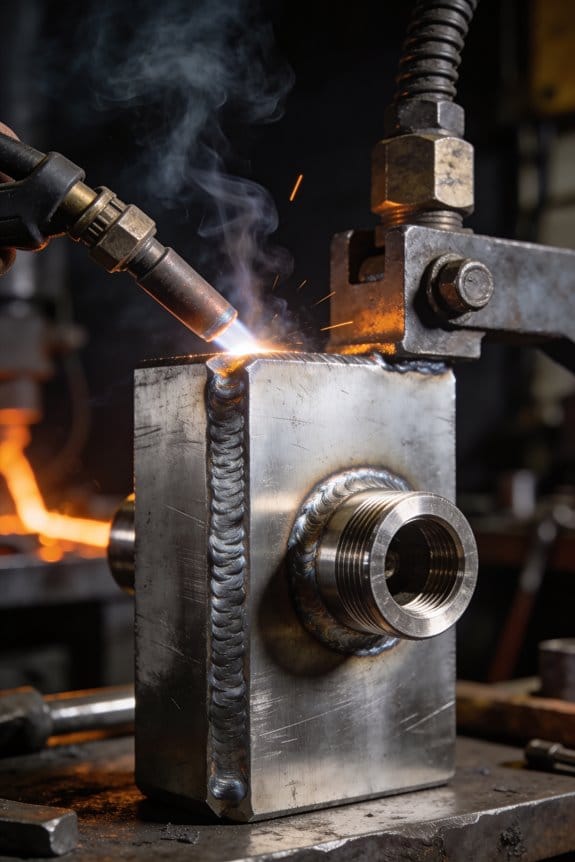
How New Materials Are Changing MIG Welding Requirements

You’re staring at a run of aluminum parts with porosity and weak beads and you can’t figure out why the welds keep failing. The exact question is: which filler wire and shielding gas combo will stop the defects and give consistent fusion on these new alloys?
You may be interested

Most welders jump to changing travel speed or amps without matching gas and wire chemistry to the base metal. This piece will show you which filler and gas to pair with common nonferrous and stainless mixes, how to set wire diameter and transfer mode for given thicknesses, and how to test and record settings that reproducibly work.
You’ll be able to set a reliable recipe and avoid wasted parts. It’s easier than you think.
Key Takeaways
If you’ve ever switched to a new alloy and had the weld crack, this explains why.
Why it matters: you can lose strength or get hot‑crack failures if filler and heat aren’t matched.
Example: welding a 7000‑series aluminum bike frame with the wrong wire and high heat can split the joint.
1) Match filler metal and adjust heat:
- Step 1: pick a filler within the alloy family (for high‑strength steels use an ER80S‑X grade; for 7xxx aluminum choose a 7055/7075‑compatible filler).
- Step 2: reduce heat input by 10–20% compared with older steels — lower voltage or faster travel.
- Step 3: weld a 50–100 mm test coupon and measure hardness across the HAZ.
Tip: if you see hardness drop >10 HRC or cracks, change filler or cut heat again.
Think of oxide on aluminum like a tiny brick wall.
Why it matters: oxides prevent fusion and cause porosity, so you won’t get strength or looks you expect.
Example: a 3 mm 6061 truck rim welded with poor prep will show pinholes and weak bead areas.
1) Clean and set up for aluminum:
- Step 1: remove oxide with a stainless brush dedicated to aluminum or use chemical etch.
- Step 2: use a spool‑gun or push‑pull feeder for wires ≥0.9 mm; for 0.8 mm use a short liner and tensioned feeder.
- Step 3: set shielding to 100% Argon at 12–20 L/min for typical torches; increase flow to 18–25 L/min on windy outdoor jobs.
Tip: if you get spatter or poor feed, try 0.035″ wire and check liner length.
The difference between stainless fusion and duplex fusion comes down to heat and gas.
Why it matters: wrong gas or filler leaves you with poor fusion or corrosion problems.
Example: welding duplex piping indoors with 98% Ar + 2% O2 yielded lack of fusion on the root pass.
1) Choose gas and filler:
- Step 1: for austenitic stainless use Ar + 2–4% CO2 or pure Argon with ER308/309 filler.
- Step 2: for duplex, use tri‑gas (Ar + 2–3% O2 + 2–3% N2) or higher heat with duplex‑rated ER2209 filler.
- Step 3: increase preheat or travel speed if fusion is poor; measure penetration on a 100 mm test bead.
Tip: if you see excessive ferrite or sigma phase, lower heat or adjust filler.
Before you weld coated or heavily corroded metal, clean it first.
Why it matters: contaminants cause porosity and weak welds, so you’ll waste wire and time otherwise.
Example: a galvanized sheet car panel welded without removal produced fly‑ash pores across a 200 mm seam.
1) Prep and wire choice:
- Step 1: remove coatings mechanically or with a solvent; grind to bare metal on the joint area for at least 10 mm each side.
- Step 2: use flux‑cored or metal‑cored wire designed for contaminated surfaces (look for manufacturer’s code for weldability).
- Step 3: run a 100–150 mm practice weld to check for porosity before final welding.
Tip: if pores persist, increase cleaning width and bake the part if moisture is suspected.
You don’t need fancy equipment to weld thin, multi‑material joints if you control wire and settings.
Why it matters: thin or mixed metals burn through and warp unless you adjust technique.
Example: joining a 1 mm stainless shim to a 2 mm aluminum bracket without control will melt the shim in one pass.
1) Thin‑joint technique:
- Step 1: switch to smaller wire 0.023–0.030″ (0.6–0.8 mm) for thinner sheets.
- Step 2: use short‑circuit or pulsed modes with low heat — reduce amps by 30–40% from standard for the same wire diameter.
- Step 3: frequently test welds on scrap the same thickness and adjust travel speed in 10 mm increments.
Tip: clamp parts tightly and use backing strips to prevent burn‑through.
Quick MIG Welding Decision Matrix: Match Material → Gas → Wire → Mode
If you’ve ever stood in front of a welder wondering what to pick, this will clear it up quickly: the material you weld determines the gas, wire, and transfer mode, and those choices change weld quality and how easy the job is.
Why this matters: choosing the wrong combo wastes time and ruins welds. Example: welding a 0.9 mm car body panel with 100% CO2 will burn through the thin sheet and make a mess.
1) Identify material and thickness (do this first)
- Step 1: Check the base metal and its thickness with a caliper or ruler.
- Step 2: Note if the metal is clean, painted, or galvanized.
- Example: mild steel, 1.2 mm thick, scratched clean to bare metal.
Why this matters: material and thickness tell you what gas and wire will give proper fusion. Example: a 3 mm mild steel door hinge needs deeper penetration than a 0.8 mm panel.
2) Pick gas and wire for common materials
- Step 1: Mild/low‑carbon steel, 0.6–6 mm: use 75% Argon / 25% CO2 with ER70S‑6 wire for smoother beads and less spatter.
- If you need more penetration and you’re roughing outside, use 100% CO2 with the same wire.
- Example: repairing a 3 mm trailer floor panel outdoors — choose 100% CO2 and ER70S‑6.
- Step 2: Thin sheet steel under ~1 mm: drop CO2 or go to 100% Argon with very thin wire (0.6 mm) to avoid burn‑through.
- Example: spot repair on a 0.8 mm hood skin — 100% Argon, 0.6 mm wire, low heat.
- Step 3: Stainless steel (any thickness): use 98% Argon / 2% O2 or 98% Ar / 2% CO2 with ER308/309/316 wire depending on grade.
- Example: fixing a 2 mm 304 stainless bracket — 98/2 Ar/O2 with ER308L.
- Step 4: Aluminum: use 100% Argon and a spool gun or push‑pull for wire feed; use ER4043 or ER5356 depending on alloy.
- Example: welding a 2 mm 6061 alloy panel — 100% Argon with ER5356, spool gun.
- Step 5: Outdoor or windy conditions: use flux‑cored self‑shielding wire (e.g., E71T‑11) to avoid carrying gas.
- Example: patching a fence post in wind — E71T‑11 flux‑cored wire.
Why this matters: matching gas/wire affects bead shape, penetration, and corrosion resistance. Example: wrong filler on aluminum causes cracking later.
3) Choose transfer mode for penetration and spatter control
- Step 1: Short‑circuit transfer for thin material and low heat; use with 0.6–0.9 mm wire, run low amperage.
- Example: panel work on 0.7 mm steel — short‑circuit at ~40–55 A with 0.8 mm wire.
- Step 2: Globular transfer gives more penetration but lots of spatter; avoid it for finish work.
- Example: heavy structural seams where appearance doesn’t matter — globular with higher current.
- Step 3: Spray transfer for deep penetration and low spatter; requires mixed gas (Argon/CO2) and higher current.
- Example: butt weld on 4 mm mild steel — spray transfer at ~180–220 A with 1.0 mm wire.
- Step 4: Pulsed spray for precise heat control and thinner parts with spray‑like benefits; choose pulse settings per machine manual.
- Example: 2 mm stainless tube welds on a bike frame — pulsed mode to control heat.
Why this matters: transfer mode controls how molten metal crosses the arc, which affects strength and cleanup. Example: using short‑circuit on thick plate leaves lack of fusion.
4) Tune parameters and plan the weld
- Step 1: Set wire diameter to match thickness: 0.6–0.9 mm for sheet, 0.9–1.2 mm for general work, 1.2–1.6 mm for heavy plate.
- Step 2: Start with these baseline currents (adjust by machine and wire): 0.6 mm ≈ 40–80 A, 0.8 mm ≈ 60–120 A, 1.0 mm ≈ 100–180 A, 1.2 mm ≈ 140–240 A.
- Step 3: Set voltage to match wire feed: increase voltage for flatter beads, reduce for a more convex bead.
- Step 4: Check joint fitup and tack welds to control distortion.
- Example: fabricating a 3 mm bracket — use 0.9 mm wire, ~140 A, medium voltage, tack at 25 mm intervals.
Why this matters: correct wire size and settings make welding predictable and reduce rework. Example: too high wire feed puts too much metal and creates burn‑through.
5) Practical tips and automation
- Step 1: For outdoor work, carry flux‑cored wire and a jacket for the regulator.
- Step 2: For aluminum, bring a spool gun and keep the wire clean.
- Step 3: If you automate, program consistent fits and the same torch angle, travel speed, and sequence for repeatable results.
- Example: a robotic cell welding 2 mm car brackets uses preset travel speed of 600 mm/min and 70 A short‑circuit parameters.
Why this matters: planning saves time and produces consistent parts. Example: inconsistent fitup on a robot causes porosity and rejects.
Follow this map: pick material → check thickness → choose gas and wire → select transfer mode → tune parameters. Start with the example numbers above, then tweak in small increments until your bead looks right.
Recommended Products
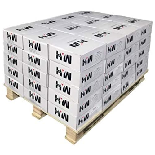
Premium Quality: Mig Welding Wire ER70S-6 adheres to AWS A5.18-05 standards, ensuring top-notch quality and performance.

Rust and Mill Scale Tolerance: The MIG wire exhibits excellent tolerance to rust and mill scale, ensuring consistent performance in various welding environments.

Do Your Best Work ... Color all your clients impressed with the precision and arc control of the ER70S-6 solid MIG welder wire. You'll love the low splatter whether you're performing single or multi-pass welds. Great for T-joints, butt welds & lap welds.
New Alloys & Nonferrous Metals : What to Change First for MIG Welding
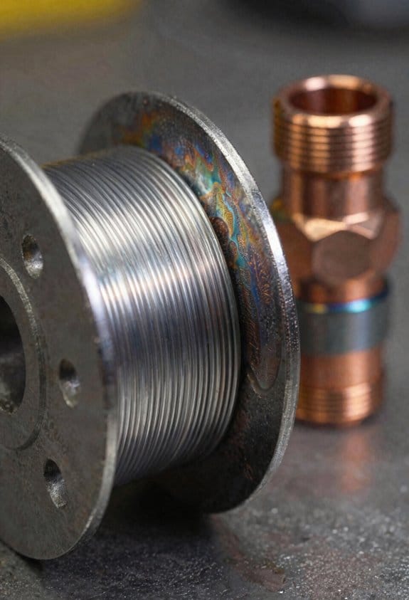
Before you switch from common steels to newer alloys or nonferrous metals, know that wrong wire or gas will ruin your welds and waste time.
1) Change shielding gas and wire first — they control arc chemistry, heat input, and fusion.
- Why this matters: using the wrong gas or wire can give you poor fusion or excess porosity.
- How to do it (steps):
- Match wire to base metal: use ER70S-6 for mild steel up to 1/4″ with 75/25 CO2/Ar for MIG; use ER4043 or ER5356 for aluminum with 100% argon; use silicon bronze or specialized copper alloys for brazing copper.
- Set gas flow: 20–25 CFH for MIG on steel, 25–30 CFH for aluminum with a cup, lower for short-circuit transfers.
- Check polarity: DCEP for steel MIG, DCEN with spool gun setups for some aluminum torches.
– Real example: when I switched from welding 3/16″ mild steel to 1/8″ 6061-T6 aluminum, I swapped to ER5356, 100% argon at 28 CFH, and the puddle suddenly wetted the joint.
2) Remove oxides on nonferrous metals before welding; oxides raise the melting point and stop wetting.
- Why this matters: if you don’t remove oxides, your filler won’t bond and you’ll get cold laps.
- How to do it (steps):
- For aluminum, use a stainless-steel wire brush dedicated to aluminum just before welding.
- For copper, file or grind the joint and wipe with acetone to remove oils.
- For brass or bronze, clean with a solvent and remove any tarnish mechanically.
– Real example: on a 1/4″ aluminum bracket, I brushed for 10 seconds per side and the bead flowed without pinholes.
3) Adjust travel speed and amperage to match conductivity and thickness; avoid excess heat that warps parts.
- Why this matters: nonferrous metals conduct heat differently, so wrong settings cause burn-through or weak fusion.
- How to do it (steps):
- Reduce amperage 20–30% vs steel for equivalent thickness on aluminum, then adjust travel speed to keep a smooth puddle.
- Use faster travel on copper because it conducts heat away quickly; increase wire feed accordingly.
- For thin sections (under 1/8″), use pulsed MIG or lower heat input and tack frequently.
– Real example: welding 3/32″ copper sheet required stepping amperage down 25% and doubling travel speed to prevent sagging.
4) Check fixturing and clamping to prevent distortion; different thermal expansion and conductivity change how parts cool.
- Why this matters: if you don’t restrain parts properly, warpage will ruin fit-up and alignment.
- How to do it (steps):
- Use more clamps and shorter stitch welds on aluminum to control shrinkage; tack every 1–2 inches on thin parts.
- Let parts cool between passes if they’re large or thin; use heat sinks or backing bars for copper.
- Measure critical dimensions before and after a test weld to quantify movement.
– Real example: clamping a 12″×6″ aluminum panel at four corners plus two center clamps kept warpage under 1/16″.
5) Test on scrap, inspect fusion and bead shape, and refine settings until the joint meets strength and appearance goals.
- Why this matters: testing prevents ruining your real part and shows how settings behave.
- How to do it (steps):
- Cut a scrap piece matching thickness and alloy, then run at least three beads with different amperage and travel speeds.
- Inspect for fusion, undercut, porosity, and bead profile; bend or break one test weld if strength matters.
- Record the successful settings (wire size, wire type, gas, CFH, voltage, wire feed, travel speed) for repeatability.
– Real example: for a butt joint on 1/8″ 6061-T6, my notes showed ER5356, 0.035″ wire, 100% argon at 26 CFH, 140–150 A, 18–20 IPM, and a steady travel speed produced a strong, shiny bead.
Final practical tip: start with the wire and gas, clean the metal, clamp well, then dial heat and speed on scrap.
Recommended Products

ER5356 .030" .035" 047" 1-LB 16-LB Aluminum Welding MIG Wire

5 IN 1 MULTIFUNCTIONAL: The MIG-205DS PRO is capable of Gas MIG/Flux Core MIG/Spool Gun Aluminum MIG/Lift TIG/Stick. (additional lift TIG torch required and spool gun required). This unit caters to a wide range of welding applications and meets your various welding needs.

ER5356, commonly referred to as “AlMg5,” is a 5% magnesium aluminum wire used for welding base metals 5050, 5052, 5083, 5356, 5454 and 5463
Shielding Gas Choices by Metal and Thickness (Argon, CO2, He Blends)
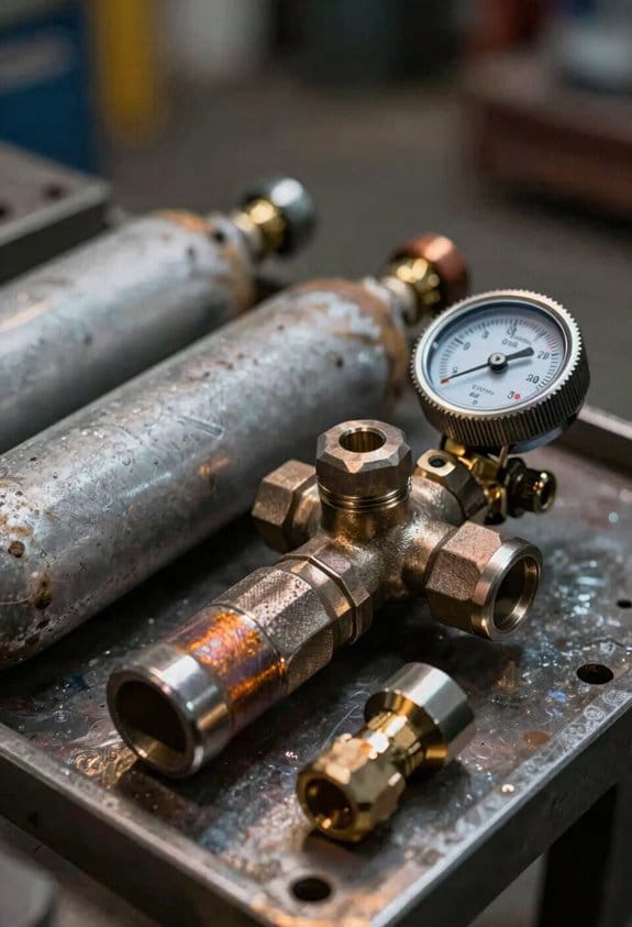
Before you pick a shielding gas, know why it matters: the gas changes your arc, penetration, and spatter so your weld either holds or fails.
If you’re welding mild steel, use these specific mixes and settings. For general work on 1/8″–1/4″ (3–6 mm), run Argon/CO2 75/25 (C25), set your MIG voltage to a medium range and use wire feed of about 300–400 inches per minute for a 0.035″ wire at 120–180 A. Example: welding a 1/4″ plate for a bracket—C25 gives a stable arc and good penetration without excessive spatter. Step 1: set gas to 75/25. Step 2: dial wire feed to 350 ipm. Step 3: tack then weld with a steady travel speed.
If you’re doing thin sheet under 14 gauge (thinner than ~1.6 mm) you need less CO2 to avoid burn‑through. Use Argon/CO2 85/15, lower amperage by 10–20%, and increase travel speed slightly. Example: patching a car fender—85/15 keeps heat down so the metal won’t warp. Step 1: switch gas to 85/15. Step 2: reduce amperage 15%. Step 3: weld in short runs.
For thick mild steel plates, use higher CO2 or pure CO2 only when you need extra penetration, but expect more spatter. For 3/8″–1″ (9–25 mm) with a single‑pass groove, try full CO2 or 60/40 Argon/CO2 with higher amperage: raise current 20–30% over your thin‑steel settings and slow down travel speed for deeper fusion. Example: joining a 3/4″ baseplate for a machine mount—CO2 helps you get through the plate in fewer passes. Step 1: set gas to CO2 or 60/40. Step 2: increase amperage. Step 3: weld slower, clean spatter between passes.
Aluminum needs 100% Argon for good wetting and arc stability; helium can help for thicker pieces. For sheet aluminum up to 1/8″ (3 mm), use pure Argon with a push technique and set wire feed to the lower side of the recommended range for your wire diameter. Example: making a hood panel—100% Argon gives the smooth bead and prevents porosity. Step 1: select 100% Argon. Step 2: use push angle and steady speed. Step 3: maintain clean oxide removal.
Stainless steel does best with high‑Argon or tri‑gas mixes when you want more heat and deeper fusion. Use Argon/CO2/He blends like 90/7/3 or Argon/Helium mixes for thick sections to increase heat input without adding too much oxidation. Example: welding a 1/4″ stainless flange—adding helium gives you the penetration without changing filler metal. Step 1: choose Argon/He or a tri‑gas. Step 2: set a higher voltage. Step 3: control travel speed for a narrow bead.
In the field, match gas to metal and thickness first, then tweak amperage and travel speed to tune bead profile and penetration. Example: onsite repair of a steel chassis—start with the gas that fits the thickness, make a test bead, then raise or lower wire feed until the bead looks right. Step 1: pick gas by metal/thickness. Step 2: run a test bead. Step 3: adjust amperage and travel speed.
One last practical tip: bring one extra cylinder per gas type when you go out, and always run a short test bead on scrap to confirm your settings before touching the real part.
Recommended Products
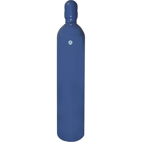

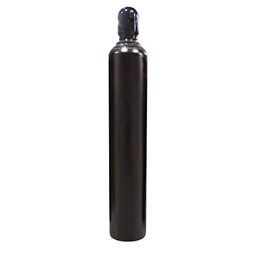
All HP cylinders come with a 10 year hydrotest date stamped.
MIG Wire Selection and Transfer Modes: Solid, Cored, Metal‑Cored, Specialty Alloys
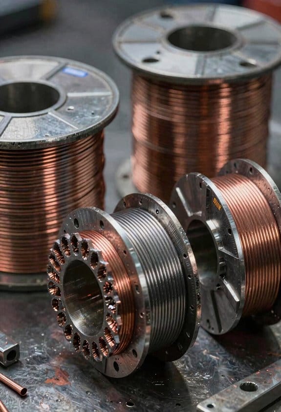
Before you pick the wire and transfer mode, know this matters because they control how deep the weld penetrates, how fast you can travel, and how clean the bead looks.
Solid wire — when to use it and how to set it up
- Why it matters: Solid wire gives predictable penetration and is easiest to feed, so you’ll spend less time fussing with settings.
- Example: If you’re welding clean 1/8″ mild steel parts for a trailer bracket in a garage, solid ER70S-6 with a 0.030″ diameter works well.
- Steps for using solid wire:
- Choose diameter: 0.023–0.030″ for thin sheet (18–14 gauge), 0.035″ for general panel and light structure, 0.045″ for thicker material above 3/16″.
- Match gas: use 75/25 argon/CO2 for good penetration and bead profile; you can use straight CO2 for deeper penetration but expect more spatter.
- Set transfer mode: short-circuit (low voltage) for sheet metal and thin joints, spray (higher voltage) for thicker joints over 3/16″ with 0.035″ or larger.
– Quick tip: If your joint is clean and you’re working indoors, go solid wire. It feeds smoothly.
Flux‑cored (tubular) wire — when to pick it and how to run it
- Why it matters: Flux‑cored wire lets you weld outside and put more metal down per pass, which saves time on fit‑up and thick joints.
- Example: Welding a rusty fence post outdoors with a flux‑cored 0.045″ E71T‑1 gives good fill and tolerates surface rust.
- Steps for flux‑cored:
- Choose type: E71T‑1 for self‑shielding outdoors (no gas), E71T‑1C or similar for gas-shielded, cleaner bead.
- Set polarity and machine: use DCEP (reverse polarity) for gas‑shielded flux cored on most machines; check your wire data sheet.
- Adjust travel speed and voltage: run slightly faster than with solid wire and bump voltage up 5–15% from a comparable solid setting to avoid undercut.
– Quick tip: For outdoor work pick self‑shielding flux core; keep a wire cleaner and brush nearby.
Metal‑cored wire — what it does and when to use it
- Why it matters: Metal‑cored wire gives higher deposition and smoother beads so you’ll get faster cycle times with less cleaning.
- Example: In a fabrication shop making handrails, switching from flux core to a 0.045″ metal‑cored wire cut grind time by half while keeping weld appearance uniform.
- Steps for metal‑cored:
- Choose wire chemistry that matches the base metal (ER70S‑MC for mild steel).
- Use mixed shielding gas (usually 75/25 Ar/CO2 or 80/20 depending on vendor).
- Set transfer: spray transfer usually yields the best bead at higher currents; use a contact tip one size larger than the wire diameter if you need smoother feeding.
– Quick tip: Metal‑cored runs best on stable, industrial machines with consistent wire feed.
Specialty alloys — matching wire and shielding
- Why it matters: If you use the wrong filler or gas on stainless or alloyed steels, you’ll ruin corrosion resistance or toughness.
- Example: Welding 304 stainless exhaust parts needs an ER308L wire and 98% argon/2% oxygen (or pure argon with pulsed settings) to avoid sensitization.
- Steps for specialty alloys:
- Identify base metal grade and pick matching filler (stainless: ER308/309/316; manganese steels: match per maker’s spec).
- Use the recommended shielding gas: stainless often needs argon with low oxygen or tri‑mix for root passes, while nickel alloys have vendor‑specified mixes.
- Watch heat input: keep travel speed up and interpass temps low to preserve alloy properties.
– Quick tip: Always check the wire maker’s spec sheet for the exact mix and filler match.
Putting it together — choose by joint and environment
- Why it matters: Matching wire type, diameter, and transfer mode to joint size, cleanliness, and location gets you fewer passes and fewer repairs.
- Example: For a dirty 3/16″ butt joint outdoors, pick 0.045″ flux‑cored self‑shielding, run at higher amperage, and overlap 1/8″ per pass.
- Steps to decide:
- Cleanliness: if the joint is clean, consider solid or metal‑cored; if dirty or outside, pick flux core.
- Thickness and speed: thin sheet — use 0.023–0.030″ solid and short‑circuit; 1/8″–3/16″ — 0.035″ solid or metal‑cored with spray; over 3/16″ — 0.045″ flux or metal‑cored with spray/pulse.
- Appearance vs. deposition: choose metal‑cored for best appearance and deposition, solid for simplicity, flux‑cored for tolerance to contaminants.
– Quick tip: Keep a spool chart on the wall with recommended wire diameter, gas, and voltage for your common jobs.
One last practical note: always test on a scrap piece at the joint fit‑up, measure penetration with a cross‑section if possible, and write the successful settings on the job sheet so you don’t guess next time.
Recommended Products
Do Your Best Work ... Color all your clients impressed with the precision and arc control of the ER70S-6 solid MIG welder wire. You'll love the low splatter whether you're performing single or multi-pass welds. Great for T-joints, butt welds & lap welds.

Premium Quality: Mig Welding Wire ER70S-6 adheres to AWS A5.18-05 standards, ensuring top-notch quality and performance.

Do Your Best Work ... Color all your clients impressed with the precision and arc control of the ER70S-6 solid MIG welder wire. You'll love the low splatter whether you're performing single or multi-pass welds. Great for T-joints, butt welds & lap welds.
Thickness‑Specific Settings and Troubleshooting Checklist (Amperage, Travel, Tips)
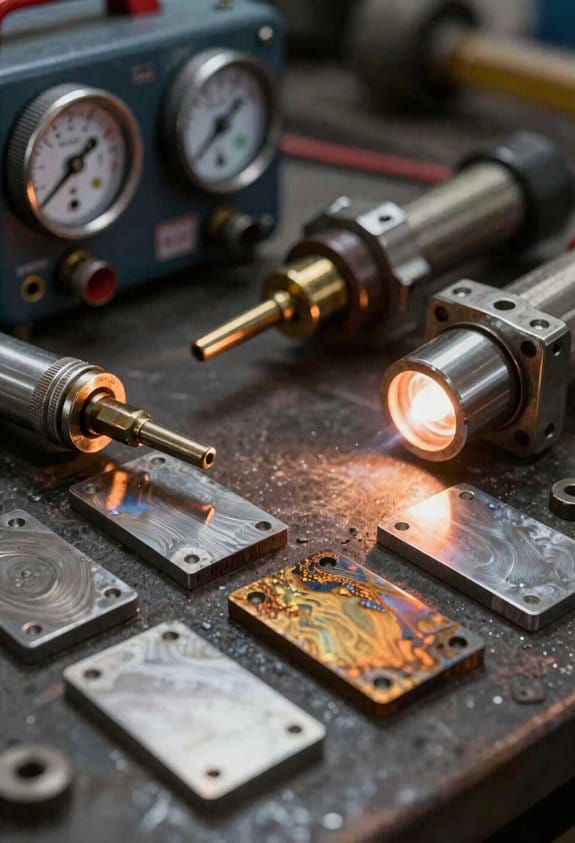
Here’s what actually happens when you change thickness on a MIG weld setting: the heat you put in controls penetration, bead shape, and whether you burn through.
Why this matters: if you don’t match settings to thickness you’ll either undercut or blow holes in the sheet.
- For 18–16 gauge sheet (0.047–0.060 in / ~1.2–1.5 mm), set machine amperage to about 50–90 A and wire feed speed (WFS) around 120–180 inches/min (ipm) with 0.023–0.030 in wire; use 75/25 argon/CO2 gas at 20–25 CFH. Example: welding a car floor patch, run 70 A and 150 ipm to avoid burn-through on the thin edge.
- For 14–12 gauge (0.075–0.109 in / ~1.9–2.8 mm), use 90–140 A and 180–260 ipm with 0.030–0.035 in wire and the same gas mix at 20–25 CFH. Example: patching a trailer side, use 110 A and 210 ipm to get good fusion without skipping.
- For 1/8–1/4 in plate (3–6 mm), jump to 140–220 A, 260–350 ipm with 0.035–0.045 in wire and a 75/25 mix at 25–30 CFH. Example: fabricating a bracket, run 180 A and 300 ipm to get full penetration through the thicker section.
How to change settings without screwing the weld: you need to ramp smoothly between thin and thick metal because sudden heat spikes cause holes.
Steps:
- Identify the thinnest and thickest sections in the joint and note their target amps and WFS.
- Program or manually ramp the amperage over the transition zone across 1–2 inches (25–50 mm).
- Start at the lower setting, slowly increase WFS as amperage climbs, and monitor bead appearance.
- If you see burn-through, back off 10–20% on amps or speed up travel 10–20%.
Travel angle and speed matter because they shape the bead and control penetration.
Why this matters: angle changes where the heat goes and speed changes how much heat is deposited.
- Hold torch at 10–20° push for thin sheet to reduce penetration.
- For thicker plate, use 15–20° work angle with a slightly flatter push to increase fusion.
- Travel speed: for thin sheet, keep it fast — about 6–12 inches/min (15–30 cm/min); for thick plate, slow to 4–8 inches/min (10–20 cm/min).
Tip cooling and nozzle care stop overheating and spatter from fouling your contact tip, which otherwise changes WFS and amps.
Why this matters: a clogged nozzle or hot tip gives inconsistent wire feed and porosity.
Steps:
- Check nozzle and tip every 30–60 minutes of welding.
- If spatter builds, remove and chisel or use anti-spatter spray; replace contact tips every 3–8 hours of heavy use.
- Keep gas flow steady at your chosen CFH and verify the regulator gauge before each run.
Troubleshooting method: isolate one variable at a time so you know what fixed the problem.
Why this matters: changing many things at once hides the real cause.
Steps:
- Set your baseline (amps, WFS, angle, gas) for the material thickness.
- If bead is too convex and undercutting, reduce amps 10–15% or increase travel speed 10–20%.
- If penetration is low or the arc is cold, increase amps 10–20% or slow travel by 10–20%.
- If spatter or burnback appears, check tip length, contact tip size, and WFS consistency.
- If porosity shows up, swap to a new gas bottle or check hose fittings for leaks.
Practical checklist (use before welding):
- Match wire diameter to material thickness.
- Set amperage and WFS per table above.
- Set gas to 20–30 CFH and check flow at the torch.
- Inspect tip and nozzle; replace if worn.
- Decide ramp length for transitions (1–2 in / 25–50 mm).
If you follow those numbers and steps you’ll get more predictable beads, fewer holes, and less rework.
Recommended Products

PORTABLE WELDER Lightweight at less than 26 Lb, operates on both 120 and 240 volts for maximum usability; Welds mild and stainless steel, 24 gauge to 5/16" (3/16" on 120V), aluminum, 14 gauge to 1/4" with a Spool Gun (included).
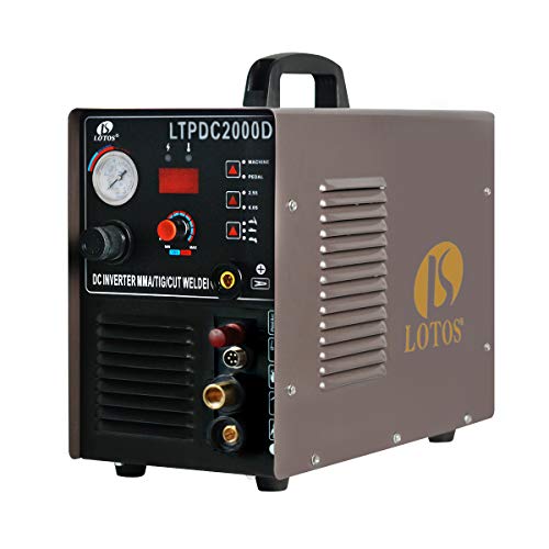
3-in-1 Multi-Process Inverter Performance: Seamlessly integrates a robust 50-amp plasma metal cutting machine, a 200-amp DC TIG welding workstation, and a 200-amp heavy-duty Stick/MMA electrical arc runner into one mobile brown framework.
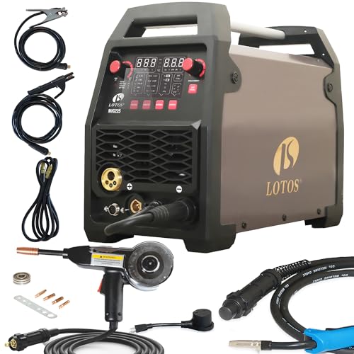
★ 𝟔-𝐈𝐍-𝟏 𝐌𝐮𝐥𝐭𝐢-𝐏𝐫𝐨𝐜𝐞𝐬𝐬 𝐖𝐞𝐥𝐝𝐞𝐫: This versatile welding machine supports multiple processes, including Gas/Solid Wire MIG (GMAW), Spool Aluminum Welding, Lift TIG (𝐓𝐈𝐆 𝐠𝐮𝐧 & 𝐬𝐩𝐨𝐨𝐥 𝐠𝐮𝐧 𝐧𝐨𝐭 𝐢𝐧𝐜𝐥𝐮𝐝𝐞𝐝), Gasless Flux Core MIG (FCAW), Stick/MMA, and Spot Welding. It’s suitable for a variety of welding needs, compatible with .023”/.030”/.035”/.040” solid & flux core wire, 035”/.040” aluminum wire.
Frequently Asked Questions
Can I Weld Coated or Painted Metals Without Removal First?
Before you weld painted or coated metal, you should know why removal matters: leaving paint or coating on the joint causes contamination that makes the weld porous, spattery, and weak.
1) Why remove coatings (one-sentence explanation): welding through paint traps gases and creates porosity that reduces joint strength by as much as 30%.
Example: if you’re welding a painted car fender for a patch panel, the tack welds will hiss and pop and the bead will blow out if the factory enamel isn’t stripped first.
2) How to remove coatings (steps):
- Step 1: Grind or sand the weld area to bare metal for at least 1 inch (25 mm) beyond the planned weld line using 60–80 grit.
- Step 2: Clean the metal with acetone or a degreaser and a lint-free rag to remove oils and dust.
- Step 3: Re-check for any paint residue under bright light; repeat grinding if necessary.
Example: for a 6-inch seam on a steel gate, grind a 1-inch strip along both sides, wipe with acetone, then tack weld.
3) Exceptions and safe shortcuts (one-sentence explanation): sometimes very thin, heat-resistant coatings can be left if the manufacturer specifically rates them for welding, but that’s rare.
– If you absolutely must weld near painted areas, cover surrounding paint with a wet rag and use short, low-heat tack welds spaced 1–2 inches (25–50 mm) apart, pausing between passes to let metal cool.
Example: when repairing a painted lawnmower deck, tack weld small spots and grind out final beads to avoid burning through the rest of the paint.
4) Safety and quality tips (one-sentence explanation): improperly removed coatings increase fume hazards and can ruin the weld, so PPE and ventilation matter.
– Wear a respirator rated for paint fumes and welding, and run a fan or exhaust to pull fumes away.
Example: while stripping paint off a metal gate, wear a P100 respirator and keep a box fan pushing air out of the garage.
Bottom line: don’t weld painted or coated metal without removing the coating first — grind a 1-inch bare-metal strip, clean with solvent, and use proper ventilation and PPE.
How Do Humidity and Weather Affect Shielding Gas Performance?
Think of humidity like invisible water in the air that changes how your shielding gas behaves.
Why this matters: moisture and weather can make your welds porous and your arc unstable, which costs you time and scrap.
Humidity pulls on your shielding gas in two ways: it adds water vapor that dilutes the gas, and it helps condensate moisture on bare metal or inside hoses. For example, welding outside after a morning fog, you’ll see more spatter and occasional pinholes in thin sheet metal. Use a drier bottle or purge your lines for 2–3 minutes before welding.
Before you pick a setup, check the weather and your workspace humidity.
- Check conditions: use a hygrometer to measure relative humidity; aim for under 60% for best results.
- If RH is above 60%: switch to a fresh bottle, shorten your gas hose to under 10 feet (3 meters) if possible, and add a windbreak.
- If you’re welding in the morning after dew: wipe metal dry and let it warm for 10–15 minutes, or apply a quick solvent wipe to remove surface moisture.
Concrete example: I once welded 0.9 mm (0.035″) stainless panels at 75% RH and had recurring porosity; after switching to a 5-foot (1.5 m) hose, purging lines 3 minutes, and moving under a pop-up tent, porosity dropped to zero.
How wind and temperature affect density and flow.
Why this matters: changes in gas density alter flow and coverage, causing your cup to suck in air or disperse gas too widely.
Cold air is denser and will require slightly higher flow; hot air is thinner and may need less. For example, welding in 40°F (4°C) morning air required me to raise flow from 20 to 22–24 CFH (9–11 L/min) to keep coverage consistent. Outdoors in 80°F (27°C) sun, I dropped from 20 to 16–18 CFH.
Practical steps:
- Adjust flow with temperature: increase by ~10% if under 50°F (10°C), decrease by ~10% if over 77°F (25°C).
- Shield against drafts: position a 3-sided windbreak so wind hits at less than a 20° angle to your weld.
- Watch for turbulence: if you see the arc wander or smoke blowing sideways, add 2–4 CFH and reposition the work or tent.
Example: Welding a structural bracket in windy, 45°F conditions, I raised flow from 18 to 20 CFH and angled a plywood board to reduce crosswind; the bead smoothed out and porosity stopped.
Preventing moisture inside equipment and cylinders.
Why this matters: water inside hoses or regulators causes inconsistent flow and can freeze in cold weather.
Steps to protect gear:
- Store spare cylinders upright in a dry room above 50°F (10°C).
- Drain or blow out hoses weekly, and after any rain exposure, purge at 5–10 CFH for 2–3 minutes.
- Use desiccant dryers or an inline moisture trap rated to 50 microns if you weld in humid environments frequently.
Real example: After installing an inline desiccant on my MIG gun I stopped getting intermittent sputter during summer nights with 68–72°F and 70% RH.
Quick checklist before a job (3 items):
- Read hygrometer — below 60% is ideal.
- Purge lines 2–3 minutes and use a hose under 10 ft.
- Set flow based on temp: ~20 CFH baseline, +10% if cold, −10% if hot.
Follow those steps and you’ll get steadier arcs and fewer rejected parts.
What Maintenance Does a Spool Gun Require Compared to a MIG Torch?
Before you start maintenance, know that keeping your spool gun clean directly prevents wire jams and inconsistent arc quality.
Spool guns need more frequent contact cleaning and wire-tension checks than a MIG torch. For example, after about 2–3 hours of continuous welding with 0.035″ aluminum wire you’ll often see dust or burn marks on the contact tip; wipe the tip with a clean rag and replace it if the hole is gouged or widened by 0.010″ or more.
Why that matters: the spool sits in the gun so dirty contacts cause feeding problems quickly. In my shop, a 20-minute job turned into an hour once because I ignored a dirty contact; cleaning fixed the feed immediately.
1) Clean contacts and nozzle
- How: unplug the gun, remove the spool, and use a brass brush or scotch-brite pad to clean the contact tip and the mating surface. Replace the tip if the orifice increases by ~0.010″.
- Frequency: every 2–4 hours of welding or after a spool change.
- Real example: after welding a trailer frame for three hours, I cleaned the contacts and restored steady wire feed.
2) Inspect and replace liner
- Why it matters: a kinked liner grabs wire and causes bird-nesting.
- How: remove the liner, visually inspect for grooves or green/black burn marks, and measure for stiffness; replace liners for aluminum every 15–25 pounds of wire or sooner if you feel resistance.
- Frequency: check at each spool change.
- Real example: swapping a chewed-up liner fixed a constant jam that fooled me for half a day.
3) Adjust wire tension
- Why it matters: too tight flattens soft wire; too loose causes slips.
- How: set tension so the feed rolls turn the wire smoothly when you pull lightly; if wire unspools too easily, increase tension in one click increments until it resists a gentle pull.
- Frequency: check at each spool change and after re-threading.
- Real example: on 0.030″ MIG wire I reduced tension one click and stopped bird-nesting.
4) Lubricate bearings and moving parts
- Why it matters: dry bearings lead to uneven feed.
- How: use a drop of light machine oil on drive bearings every 10–20 hours; avoid getting oil on the wire path.
- Real example: a noisy drive wheel went silent after one drop of oil and the feed smoothed out.
Torches (MIG gun) mainly need tip, nozzle, and liner maintenance, and you can do these less often. For typical steel MIG work:
1) Clean or replace contact tip and nozzle every 4–8 hours of use, or sooner if you see spatter building up.
2) Inspect liner every 25–50 pounds of wire or if feed feels rough.
3) Replace worn diffusers or gas cups as needed.
A quick checklist you can follow:
- Before welding: check tension, inspect liner, quick wipe of tip (takes 2 minutes).
- Every spool change: full clean and liner inspection (10–15 minutes).
- Every 10–20 hours: lubricate bearings and replace tips/nozzles if damaged.
Bottom line: your spool gun needs more hands-on checks—clean contacts, re-tension wire, and inspect liners more often—while your MIG torch needs routine tip, nozzle, and liner care on a looser schedule.
Are There Certification Implications Using Advanced Alloy Wires?
Before you use advanced alloy wires, know that your welding qualifications will probably change — because different alloys alter weld metallurgy and performance.
Why this matters: certification ensures your welds meet mechanical and metallurgical requirements. For example, if you switch from ER70S-6 mild steel wire to a high-alloy stainless filler like ER316LSi, your employer may require new procedure qualification records and welder requalification because the stainless behaves differently during cooling and can be prone to sensitization.
What you’ll likely need
- Update your welding procedure (PQR/WPS).
- Do this when the filler chemistry or base metal group changes.
- Example: a company that welds pressure vessels switched from carbon to duplex stainless and had to run a new PQR at production amperage and travel speed.
- Required tests include tensile, bend, and sometimes hardness or impact per your code or spec.
- Example: for pipeline work using a high-strength Ni-alloy, the contractor submitted Charpy V-notch impact tests at -20°C.
- If your welding position, joint design, or heat input changes, expect a new qualification coupon.
- Example: a welder qualified on solid mild steel wire had to requalify when switched to flux-cored high-Mn wire for heavier plate.
- Your employer signs off on company WPSs and may add an internal endorsement after practical tests.
- Third-party codes (ASME, AWS, API) or client specifications often require documented PQRs and welder qualifications. Have copies ready.
Who confirms competence
Practical steps you should take
- Identify the new alloy’s spec and recommended WPS limits.
- Check the code or client spec for required tests and temperatures.
- Run a PQR using the actual joint, position, and parameters you’ll use.
- Arrange mechanical/metallurgy testing and keep lab reports.
- Requalify welders with coupons that match your field conditions.
- File the updated WPS/PQR and welder records with quality.
A final example: a small fabrication shop moved to a Ni-Cr-Mo filler for corrosive service. They ran one PQR at production settings, did tensile and impact testing at service temperature, requalified two welders in flat and vertical positions, and then had the client accept the lot. That sequence saved them rework later.
If you want, tell me the wire alloy and the code or client spec you’re working to and I’ll list the exact tests and typical parameters you’ll need.
Can Robotics Change Shielding Gas or Wire Choices?
Think of robotics like a smart assistant for your weld setup: it lets your machine react to what the joint *actually* needs, not what you guessed it needed.
Why this matters: changing shielding gas or wire on the fly cuts scrap and reduces rework by matching parameters to the part.
How you do it, step by step:
- Fit the robot with a wire feeder and a gas manifold that accept remote commands.
- Add sensors — a simple voltage/current monitor plus a high-speed optical seam tracker.
- Program rules: for example, if current drops below 180 A on stainless 3 mm sheet, switch from 98% Ar/2% O2 to 90% Ar/10% CO2 and increase feed by 0.5 m/min.
- Test on a sacrificial coupon and log bead appearance and porosity for three runs.
Real-world example: a shop roboticizing MIG on 3 mm stainless exhaust brackets ran a seam tracker and current monitor; when the seam widened the controller switched to a more reactive gas mix and bumped feed rate, cutting porosity by 60% on the first shift.
Practical tips:
- Start simple: control either gas or wire first, not both.
- Use conservative thresholds (e.g., ±10% current change) so you don’t flip settings on noise.
- Record every change with time stamps so you can correlate changes to weld quality.
Why the numbers matter: for a 3 mm carbon steel part, shifting from 100% Ar to a 90/10 Ar/CO2 mix can increase transfer stability and allow wire feed to rise 0.3–0.7 m/min without spatter.
Real-world example: an automotive supplier used a rule that if short-circuit transfer time exceeded 0.8 ms, the system moved to a higher CO2 mix and increased wire speed, which reduced cycle time by 8 seconds per part and cut scrap by 12%.
Final checklist before you run:
- Verify gas manifold response time is under 500 ms.
- Calibrate wire-feed increments to 0.1 m/min.
- Validate sensor noise floor and set hysteresis around thresholds.
If you do those three checks, you’ll have a reliable, change-on-the-fly setup that improves quality and reduces waste.