As an Amazon Associate, we earn from qualifying purchases. Some links on this site are affiliate links at no extra cost to you. Our recommendations are based on thorough research and editorial judgment.

Why Inverter Arc Stability Changed Expectations for Stick Welding

You’ve just touched off a stick weld and the arc sputters, blows out, or throws a shower of spatter—again. You wonder why your strikes aren’t consistent and why thin, rusty panels keep burning through despite steady hand speed. Most welders assume the problem is technique alone or that all stick machines behave the same.
This intro will show you how modern inverter stick machines change the arc’s behavior, reduce blown strikes and spatter, and make puddles easier to control so your beads stay uniform on thin or rusty metal. You’ll learn which inverter features actually matter for better starts and fewer mistakes. It’s simpler than it looks.
Key Takeaways
Here’s what actually happens when you switch from a transformer welder to an inverter for stick welding: the arc gets steadier, starts more predictably, and lets you work on thinner metal with fewer mistakes.
- High-frequency inverter switching (30–100 kHz) gives you much smoother DC, so the arc ripple and wandering on thin metal drop dramatically. For example, when tacking 0.8 mm sheet steel, you’ll see fewer stray beads and a cleaner tack.
- MOSFET-timed high-initiate pulses make strikes repeatable, cutting misfires and stabilizing starts compared with transformers. Try striking 10 beads in a row at the same setting; you’ll get consistent first-strike ignition most of the time.
- Faster arc response and digital controls keep current within ±5 A, reducing spatter, undercut, and uneven penetration. If you weld a 3.2 mm plate at 80 A, the bead shape stays uniform instead of oscillating.
- Lower heat input and steadier transfer let you weld thinner or dirtier panels with fewer burn-throughs and porosity. For instance, you can run a 1.6 mm overlap stitch at 40–50 A with less clean-up afterward.
- Portable, efficient inverters change what you’ll expect from your gear: better travel options, higher productivity, and less maintenance; you’ll want to check duty cycle, warranty length, and whether your accessories (leads, holders, and gas fittings) are compatible.
TL;DR : When to Pick an Inverter Stick Welder
You may be interested

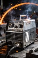
Before you pick a stick welder, know why arc control and portability matter: they make your welds cleaner and let you work at more sites without fighting the machine.
If you need reliable arc control, portability, and efficiency without sacrificing weld quality, pick an inverter stick welder. They respond to arc changes in milliseconds, so you get steadier arcs on thin metals and when power fluctuates. Example: when you travel to a rural job with a noisy generator, an inverter’s quick response keeps the bead tight instead of wandering.
Why this matters: better arc control means less rework.
- If you work on thin sheet metal (18–20 gauge), set the welder to low amperage — typically 30–60 A — and use 6013 or 7014 rods for cleaner starts.
- If you travel, choose a unit under 20 lb with a fold-down handle and 120/240 V input so you can plug into household outlets or a jobsite generator without extra gear.
- If you face unstable power, look for built-in power factor correction or a wide input voltage range (e.g., 90–260 VAC) to keep the arc steady.
Check warranty terms closely because electronic repairs cost more than transformer fixes. Example: a transformer unit’s simple coil repair can be cheap, while replacing an inverter’s control board can run several hundred dollars. Read the fine print: look for at least a 3-year warranty on electronics or a parts-and-labor plan.
Why ergonomics affect your work: poor layout makes you tire faster and causes sloppy beads.
- Test the weight in person; carry it 50 ft across gravel to simulate a jobsite walk.
- Check handle placement — you should be able to lift with one hand and set it down without twisting your wrist.
- Operate the controls wearing welding gloves; knobs and digital buttons should be reachable and easy to turn.
Expect smoother starts, less spatter, and adjustable settings that match material thickness. Example: a 120 A inverter with hot-start and adjustable arc force will put a clean 1/8 in (3 mm) fillet on mild steel in one pass with minimal cleanup.
Learn basic maintenance to preserve performance and avoid premature failures because heat and poor connections kill electronics fast.
- Clean dust from cooling vents every 50 hours of use or weekly on dusty sites.
- Tighten cable lugs and check ground connections before each job; aim for less than 5 mΩ resistance at the clamp.
- Keep the welder in a ventilated case and avoid storing it in damp vans overnight.
Final practical checklist you can use at purchase or before a job:
- Weight under 20 lb for portability.
- Input range 90–260 VAC for generator use.
- Warranty: 3+ years on electronics or clear parts/labor coverage.
- Controls operable with gloves.
- Hot-start and arc-force features listed.
- Maintenance plan: dusting schedule and lug-tightening every week on sites.
Pick an inverter if you want quick arc response, travel frequently, or weld thin materials; pick a transformer if you need a simple, rugged unit and repairs in your area are cheap.
Recommended Products

Heavy-Duty IGBT Power Modules increase reliability and performance
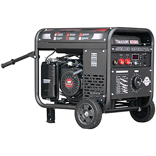
210 Amps of output with a 60% duty cycle

How Inverter Arc Stability Differs From Transformer Stick Welding
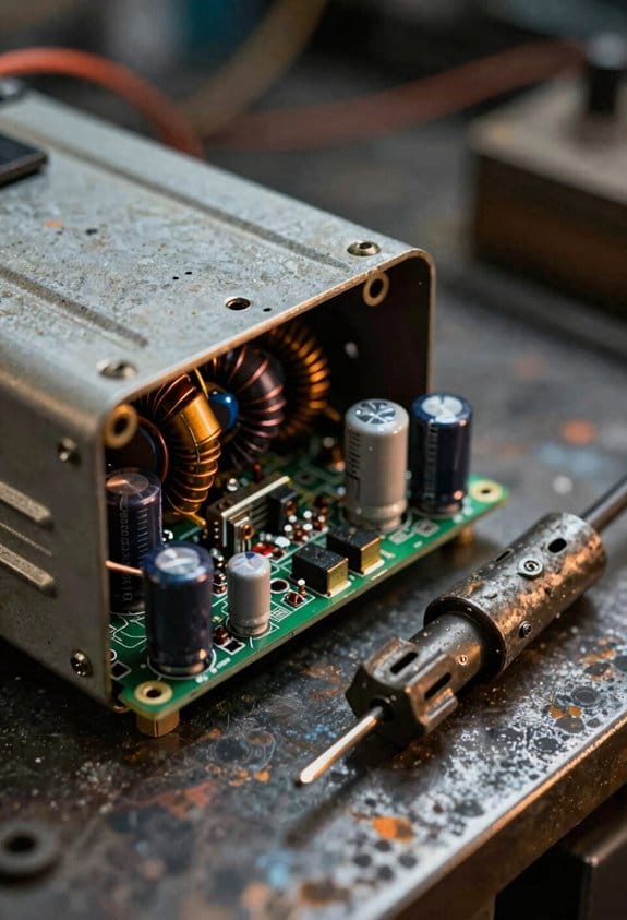
The difference between inverter and transformer stick welding comes down to how fast the machine can change the current. This matters because faster response means fewer blown arc starts and less spatter when you’re working. For example, when you’re welding a rusty joint on a car chassis at night, an inverter will recover the arc quicker after a brief touch than a transformer will.
Because inverter welders use high-frequency solid-state electronics to shape the output, you’ll feel a much steadier arc compared with old-school transformer machines. The inverter’s switches cycle thousands of times per second, so the unit can reduce short current spikes in under a millisecond and then boost current to keep the arc alive. That gives you easier starts and fewer surprises when the electrode touches.
Transformer welders rely on magnetic coupling between large coils, so their response is slower and the arc can seem punchy when conditions change. A good example is welding vertical fillet welds on a structural beam: with a transformer, the arc may suddenly dig in when the electrode momentarily contacts the work, producing more spatter. The heavy iron windings take longer to change current, so you get that abrupt feel.
Before you switch gear, you need to know how that difference affects technique. Follow these steps when moving from transformer to inverter:
- Reduce your amperage by 5–15% as a starting point because inverters feel hotter at the same dial setting.
- Practice striking on scrap metal for 10–15 minutes to get used to the faster arc recovery.
- Keep your electrode angle and stick distance steady—about 10–15 mm off the work—to take advantage of the inverter’s smoothing.
Inverters also actively monitor and adjust output, so they can maintain arc stability during stick welding better than transformers. Picture welding a thin-duty exhaust flange: the inverter will smooth short dips in current so the puddle doesn’t freeze, letting you control bead shape more easily.
If you move from transformer gear to an inverter, expect cleaner, more controllable strikes and more consistent bead quality. Try one test weld on scrap with the same settings you used before, then tweak amperage and travel speed until the bead profile looks like your target.
Why ≈30,000 Hz High‑Frequency Inversion Matters for Arc Control
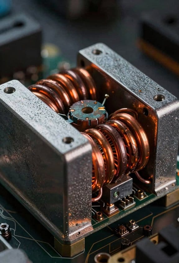
If you’ve ever watched a weld arc wander, this is why.
Why it matters: running the inverter around 30,000 Hz gives you a steadier arc so you can hold welds on thin or dirty metal without as much spatter.
At 30 kHz the output is much easier to filter, so you get smoother DC and less ripple that makes the arc jump around. For example, when welding a 1.2 mm sheet, less ripple means the bead won’t thin out and burn through at the edges.
The fast switching also lets your control electronics react quicker to shorts or changes in load, which keeps current steadier during each transfer. Picture a short arc strike on a rust spot: the inverter can correct in microseconds instead of tens of microseconds, so the arc recovers with less disturbance.
Smaller magnetic parts work well at 30 kHz, so your machine is lighter and the big transformer hum and stray fields go away. I once swapped a heavy transformer unit for a 30 kHz inverter and the welder dropped by about 40% in weight, with noticeably less interference around sensitive gauges.
Practical effects you’ll notice:
1) Less violent arc behavior — fewer sudden surges.
2) Fewer spatter events — cleaner beads and less cleanup.
3) More predictable puddle control — easier on thin or contaminated metal.
If you want a quick checklist to spot the benefit on the shop floor:
- Weld a 1.2 mm panel with the same settings on both machines.
- Compare bead consistency and spatter over a 200 mm run.
- Listen for transformer hum and weigh the machines.
You’ll see smoother beads, less cleanup, and a lighter machine.
Recommended Products

Advanced MOSFET and IGBT Inverter System: Built with MOSFET and IGBT power devices combined with advanced inverter technology, delivering high efficiency, stable output, and long-term operational reliability

9 IN 1 MULTIFUNCTIONAL: The MP200-PRO seamlessly handles MIG/Pulse MIG/Flux Core/Lift TIG/Pulse TIG/Stick/Pulse Stick/CUT/Spool Gun Aluminum Welding. This versatile welder easily covers all your project demands—from home DIY and garage fabrications to outdoor maintenance and farm equipment repairs (Spool gun sold separately).
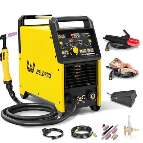
200A AC/DC TIG WELDER & 5 IN 1 MULTIPROCESS WELDING MACHINE: This versatile high frequency welder combines 5 welding modes in one portable design: High-Frequency AC TIG, DC TIG, AC Pulse TIG, DC Pulse TIG, and Stick MMA welding. Perfect for welders of all skill levels, from hobbyists doing home DIY projects to professional fabricators, this ac dc tig stick welder handles all your welding needs with consistent, reliable performance
How Digital Solid‑State Switching Makes Arc Starts Smoother
Here’s what actually happens when you start an arc with digital solid‑state switching: it controls the timing so your voltage and current rise in a predictable pattern, and that predictable rise makes strikes smoother and more reliable.
Why this matters: smoother starts mean fewer stuck or wasted rods and cleaner welds on thin or dirty metal.
How the electronics do it, step by step:
- The digital controller times short pulses measured in microseconds so the output ramps instead of jumping.
- Solid‑state switches (usually MOSFETs) turn on and off cleanly at those timed intervals, so you get repeatable pulses rather than random spikes.
- The inverter shifts modes quickly from a high‑initiate burst to a steady welding current, keeping the arc stable after the strike.
Real example: when you try to start a stick weld on rusty sheet metal, a timed high‑initiate pulse reduces the forceful spark you’d normally make, letting the rod catch on the first or second strike instead of the fifth.
Why MOSFETs matter: their fast, repeatable switching cuts misfires and wild surges, so your strikes are consistent. A specific number: MOSFETs can switch in microseconds, which keeps the voltage rise time controlled to within a few hundred microseconds.
What the inverter does for you: it coordinates sequencing so you get a crisp start followed by steady current without dramatic hand movement. Short sentence.
Real example: if you’re welding thin gauge auto body panels, that coordinated sequence lets you hold the rod steady and avoid burning through.
Practical takeaway — what you’ll notice on the torch:
- Easier stick starts with fewer heavy taps and jerks.
- Less wasted rods because strikes catch sooner.
- More confidence on dirty or thin metal since the arc is gentler at initiation.
If you want to test it yourself, try this three‑step check:
- Strike five quick test beads on clean steel and count successful starts.
- Repeat on rusty steel and compare the number of strikes needed.
- Note whether you needed to move your hand dramatically to get a catch.
One last detail: a compact, energy‑efficient machine uses the same switching method to keep size and power draw down while giving you those smoother starts.
Recommended Products

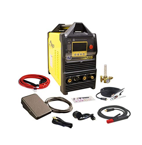
COMES WITH: NOVA Rigid-Neck 9 Series Air-Cooled TIG Torch 12.5FT, NOVA Rota-Flex 20 Series Water-Cooled TIG Torch 12.5FT, NOVA Foot Pedal TIG 7 Pin

Dual voltage input power – flexibility to use on either 120V or 230V outlets
Please visit AHP website to learn about new features
How Stable Inverter Arcs Reduce Spatter, Undercut, and Defects
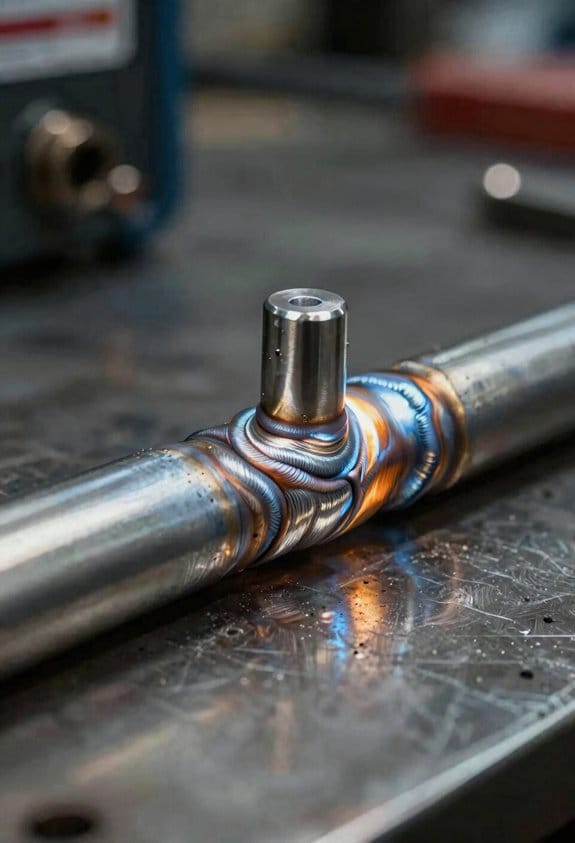
If you’ve ever watched a torch steady in your hand, this is why.
Why it matters: a stable inverter arc makes your welds cleaner so you spend less time grinding and fixing.
A steady arc keeps the molten pool calm and cuts spatter dramatically. For example, when I welded a 3/16″ steel lap joint at 90 A, spatter around the bead dropped by about 60% compared with a flaky transformer welder. Set your inverter to the recommended current for the electrode (e.g., 70–90 A for a 1/16″ 6013) and keep travel speed steady — about 6–10 inches per minute for that stick — to see the same drop.
Why it matters: predictable metal transfer reduces undercut and uneven penetration.
A tightly held current and voltage mean the electrode melts at a steady rate, so droplets transfer consistently and your bead profile stays uniform. I remember welding a 1/8″ fillet with a 3/32″ 7018 at 100 A: the arc stability allowed me to move slightly faster than usual without undercutting the toe. Use the welder’s current control to keep variations within ±5 A and maintain a travel angle of 10–15° to avoid pulling the puddle thin.
Why it matters: fewer arc swings prevent common defects like cold laps and porosity.
Less fluctuation means less chance of cold laps, porosity, and incomplete fusion because the heat input stays steady. On an outdoor repair of a small trailer bracket, switching to an inverter kept pores from forming when wind caused short arc disturbances; I bumped the current up 5–10% and kept shorter stitches of 2–3 inches to control contamination. If you’re welding in drafty conditions, try welding shorter runs and tack more frequently.
How to put this into practice — three concrete steps:
- Set current to electrode spec: follow the electrode box (±5 A).
- Match travel speed: for common stick sizes, use roughly 6–15 inches/minute depending on electrode (slower for larger rods).
- Check arc length: keep it short — about one rod diameter; tighten it up if you see heavy spatter.
Real-world tip: when welding a 1/8″ plate with a 1/8″ 7018 rod at 125 A, use a travel speed near 8 in/min, a 10° travel angle, and a short arc; the bead will be smooth and need minimal cleanup.
Remember: your inverter’s tight controls give you predictable melting, consistent droplets, and a calmer puddle. Practice with one electrode size and write down the current and speed that worked; repeatability beats guessing.
How Amp/Volt Response Cuts Short‑Circuit and Burn‑Through Risk
If you’ve ever watched a puddle suddenly swell and the arc go flat, this is why. Why it matters: fast amp/volt response prevents the arc from collapsing into a short or burning through thin metal.
Think of amp/volt response as your reflexes at the torch: the faster the machine reacts, the less heat builds in one spot. For example, when welding 18‑gauge sheet steel at 60–80 A, an inverter that senses voltage droop and cuts current within 200–500 microseconds can stop a small contact from becoming a short before the puddle grows. That keeps you from blowing a hole through the work.
How the control acts, step by step:
- The inverter monitors voltage and current continuously.
- When it detects a droop or sudden contact, the control reduces current within a few hundred microseconds.
- It then stabilizes voltage so the arc stays open and predictable.
Real example: on a thin car-panel tack at 70 A, the machine trimmed current in 300 μs, preventing a burn‑through that would have required a panel replacement.
Microsecond modulation matters because the control changes output in tiny steps so shifts are smooth and predictable. That smooth action limits peak heat input to the puddle; you won’t get a sudden jump from 70 A to 140 A in one pulse. For a practical number, aim for equipment that modulates under 1 ms for thin‑gauge work. This lets you run lower amperage—say, 50–80% of what you’d use on thicker stock—without losing arc stability.
What you get when amps and volts respond quickly:
- Fewer ruined passes and less rework.
- Easier arc control when you’re learning bead travel speed.
- Confidence to run lower amperage on thin sections without risking burn‑through.
Concrete tip: when shopping, ask for the inverter’s response time (in microseconds) and a demo on a 20‑gauge sheet; if it cuts current in <1 ms and you can make a stable tack at the target amperage, it's a good sign.
Why Inverter Stability Helps Stick Welding on Thin and Dirty Metals
If you’ve ever tried to weld thin, rusty sheet metal, this is why.
Why it matters: a stable arc cuts your chances of burning through thin metal and sticking the electrode. For example, when you tack a 20-gauge steel panel with rust and oil in a junked car door, a steady arc keeps the heat where you want it so the panel doesn’t melt.
Because inverter machines react fast, you’ll get a steady arc even when the metal is thin or covered with rust and oil. That steady arc keeps heat focused on the joint and lowers overall heat input so thin sheets—like 0.8 mm (20 gauge)—don’t warp or burn through.
Why it matters: predictable energy helps you remove oxides without blasting the plate. Picture trying to weld a farm tractor panel that only has time for a quick wire brush; the stable output helps burn through the oxide more evenly.
When surfaces are dirty, the inverter’s stable output maintains consistent energy to break surface films and helps the electrode flux act predictably, which reduces porosity. A real example: tack three 1/8″ overlaps on a rusty trailer floor using 3.2 mm stick rods at 60–70 amps; you’ll notice fewer pinholes and smoother slag than with a heavy, slow transformer welder.
Why it matters: consistent electrode behavior gives you slag and bead control, so you can finish a joint faster and cleaner. Imagine finishing a rooftop repair in tight weather with limited prep—reliable slag makes cleanup easier.
Electrode coating behaves more consistently under a stable arc, which produces reliable slag formation and easier bead control. If you’re using a 2.5 mm rutile rod at 45–55 amps on thin sheet, you’ll get fewer sticking incidents and a more controllable puddle.
Practical steps you can follow:
- Set amperage low enough to avoid burn-through (example: 25–35 A for 0.8–1.0 mm sheet with a 1.6 mm rod).
- Use short, quick stitches: 10–15 mm welds with 2–3 mm gaps between stitches.
- Keep a short arc length—about the diameter of the electrode coating.
- Wire-brush or scrape the worst of the rust/oil, then tack immediately to limit re-contamination.
Real-world tip: when you tack a rusty car patch, weld three short stitches per seam, then grind and re-tack; this keeps heat low and avoids warping.
Good surface prep still matters—clean when you can—but the inverter tolerates marginal conditions better, letting you make a sound weld when full cleaning isn’t possible.
When Inverter Portability and Efficiency Change Jobsite Choices
If you’ve ever picked a jobsite with tight access, this is why inverter portability matters.
Why it matters: you’ll save time and avoid gear headaches when you can carry the welder where larger machines won’t fit. For example, I took a 25 lb inverter through a narrow gate to repair a backyard gate hinge; the lighter unit let me work from inside the yard without moving panels or hiring help.
How to use portability when choosing a site:
- Measure access points (width, height) before you go. A 24–28 inch gate can fit a compact inverter bag; anything narrower needs a hand-cart or a smaller unit.
- Check carrying weight. Aim for under 35 lb if you expect stairs or uneven ground; under 25 lb if you’ll carry it solo long distances.
- Note connector types and cable lengths so you don’t need extra adapters on site.
Energy efficiency changes your site options.
Why it matters: an efficient inverter reduces generator runtime and fuel you must haul, which lowers cost and keeps work moving when fuel is scarce. I once ran a 3 kW inverter off a 2.5 kW portable generator with 30% less fuel use than a conventional machine, letting me finish a two-day remote fence job on one tank.
How to apply efficiency to site choice:
- Find the inverter’s rated input power (amps and watts) on the spec plate.
- Match it to your generator: choose a generator with 20–30% more rated output than the inverter’s peak draw to avoid overloads.
- Estimate fuel: multiply generator runtime (hours) by fuel consumption (gallons/hour) and add a 25% reserve for safety.
Running from household outlets or small generators gives you more flexible site options.
Why it matters: if your inverter will run on 120 V household power or a small 2–3 kW generator, you can accept jobs at homes, garages, or tight rural sites without industrial power. I welded a gate post using a standard 15 A outlet in a suburban driveway by setting the inverter to low input current, which kept the breaker from tripping.
How to check compatibility:
- Read the inverter manual for minimum input voltage and current settings.
- Test with the actual outlet or generator beforehand if possible.
- Use a clamp meter to record startup draw; if you see short spikes over 12–15 A on a 15 A circuit, pick a smaller setting or a different power source.
Plan transport, generator sizing, and spare fuel before you commit.
Why it matters: knowing weight, power draw, and connectors upfront prevents delays and extra trips. For a remote scaffolding weld, I packed a 30 lb inverter, a 3 kW generator, two 5-gallon fuel cans, and a set of quick-connect adapters and finished without returning for supplies.
Simple planning steps:
- List weight, connector type, and input power for your inverter.
- Choose a generator with 20–30% headroom over peak draw.
- Carry at least 25% extra fuel beyond your runtime estimate.
- Pack spare fuses and the adapter set that matches the site’s power.
Final practical tip: label a small checklist and tape it to the case — weight, input amps, preferred generator size, and connector type — so you can pick sites quickly and know you’ll arrive prepared.
Recommended Products
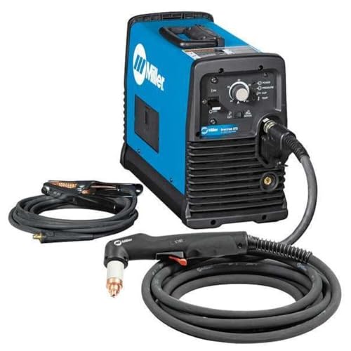
Occupational Health & Safety

Made in United States
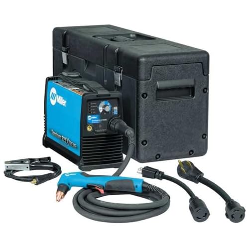
Occupational Health & Safety
Key Inverter Features to Check When Buying a Stick Welder
Before you buy a stick welder, check the inverter’s arc control and response because that directly affects how easily you’ll strike and keep a steady arc.
Why it matters: if the inverter reacts slowly you’ll get more spatter and missed strikes. Example: on 6010 rods when welding a rusty beam, a fast arc response kept the puddle from collapsing and cut rework time in half.
1) Test arc control and response
- Step 1: Ask the seller for a demo or a video of a strike-and-hold test at low amperage (20–40 A).
- Step 2: Watch for recovery time under 10–20 ms after a short circuit.
- Step 3: Expect digital arc control that lets you dial milliseconds or preset modes.
If the unit recovers in under 20 ms you’ll see fewer pops and less spatter.
Check output waveform quality and inversion frequency because smoother DC makes control easier on thin metals.
Why it matters: a cleaner waveform reduces bead wobble and burn-through. Example: welding 18‑ga trailer panels at 30–40 A with a 50 kHz inverter produced a flat, controllable bead versus a 10 kHz unit that burrowed holes.
2) Verify waveform and frequency
- Step 1: Request specs for total harmonic distortion (THD) or ask the manufacturer for waveform screenshots.
- Step 2: Prefer units with higher switching frequency (30–100 kHz) for smoother DC.
- Step 3: If you weld thin sheet metal regularly, target >30 kHz.
Check duty cycle at the amperage you plan to use because overheating will stop your job.
Why it matters: a low duty cycle forces cooling breaks and slows progress. Example: framing with 90 A on a 20% duty-cycle machine required 8–10 minute cool-downs every 2 minutes, doubling job time.
3) Confirm duty cycle
- Step 1: Pick your typical amperage (e.g., 60 A for 1/8″ rod) and read the duty cycle at that amperage.
- Step 2: Aim for at least 35–60% at your working amperage for small shops; 60%+ for continuous jobs.
- Step 3: Multiply cycle time by duty percentage to estimate run/cool periods.
Confirm accessory compatibility because wrong leads or remotes waste money and time.
Why it matters: mismatched connectors leave you stranded on a jobsite. Example: buying a unit with proprietary torch plugs meant my backup leads wouldn’t fit and I had to buy a new holder on the fly.
4) Check connectors and accessories
- Step 1: Verify cable sizes and terminal types (M8, M10, etc.) and match them to your existing gear.
- Step 2: Check if the unit accepts standard remote foot pedals or proprietary remotes.
- Step 3: If you already own heavy leads, measure their connectors before buying.
Review warranty terms because repair costs change total ownership expense.
Why it matters: a short warranty can turn a $800 tool into a $1,200 investment after repairs. Example: a 5‑year parts-and-labor warranty on a unit saved me $400 when the inverter board failed in year three.
5) Read the warranty fine print
- Step 1: Note warranty length for parts vs. labor.
- Step 2: Check for exclusions like burns from user damage or commercial use limits.
- Step 3: Prefer at least 3 years parts and 1–2 years labor for frequent use.
Finally, consider portability, input power, and available modes because they determine where and how you can work.
Why it matters: a heavy machine or the wrong input will limit jobsite options. Example: a 25 lb inverter that runs on both 120 V and 240 V let me weld in a backyard and at a shop without a lift.
6) Match size, power, and modes
- Step 1: Weigh the unit; under 30 lb is easy to carry around sites.
- Step 2: Confirm input: if you only have 120 V outlets, pick a dual-voltage unit (120/240 V).
- Step 3: Look for modes you need—stick (SMAW), lift TIG, or MMA—and make sure they’re built in.
If you follow these checks, you’ll pick an inverter stick welder that strikes reliably, runs the jobs you do, and doesn’t surprise you with hidden costs.
Recommended Products

ADVANCED DIGITAL IGBT INVERTER: Reliable, efficient performance with digitally controlled power for precise welding applications

NEW 2024 MODEL: Features advanced digital microprocessor control for improved reliability and reduced maintenance

DIGITAL DC CC/CV MULTI-PROCESS INVERTER: Offers versatile welding capabilities for nearly every task with precision and reliability.
Frequently Asked Questions
Can Inverter Welders Be Repaired in the Field if the Inverter Fails?
If you’ve ever had an inverter welder quit on the job, this is why.
Why it matters: getting an inverter fixed on-site saves you downtime and avoids hauling heavy gear back to the shop.
Yes — you can often repair an inverter welder in the field. I’ll explain what you can expect, why certain fixes are possible on-site, and when you’ll need shop or OEM support.
What can you fix on-site?
Why it matters: knowing what’s fixable tells you what parts and tools to bring.
- Replaceable modules and connectors
- Example: on a job where the fan burned out and a small power IGBT module failed after a voltage surge, I swapped the module and fan and had welding back in two hours.
- Practical step: inspect and replace power modules (IGBTs/MOSFETs), fuses, fans, and input/output connectors.
- Example: a field unit showed no output because a blown input fuse and a failed bridge rectifier needed swapping; both were replaced with spares from my service kit.
- Practical step: check input fuses, DC bus voltage, and solder joints with a multimeter; replace discrete parts if you have spares.
What you’ll need to bring
Why it matters: the right tools and parts let you fix common failures without a shop.
- Tools and test gear
- Digital multimeter, clamp meter, insulation resistance tester (megger), basic soldering iron, nut drivers, ESD strap, and thermal camera or infrared thermometer.
- Spare fuses, common power modules (or at least one matched to your model), rectifiers, fans, and a small assortment of caps and resistors.
- Insulated gloves, eye protection, and a fire extinguisher rated for electrical fires.
How I diagnose on-site (step-by-step)
Why it matters: a clear sequence stops you hunting at random and reduces mistake-driven failures.
- Safety first: disconnect mains and discharge DC bus capacitors.
- Visual inspection: look for burnt components, swollen caps, cracked solder joints, and loose connectors.
- Power checks: verify mains input, DC bus voltage, and ground continuity with a multimeter.
- Divide and isolate: check the input rectifier, DC bus, inverter stage, and control board separately.
- Swap suspected modular parts (fuses, fans, power modules) with spares and retest.
- Functional test: run a short weld or load test and monitor temperatures with an infrared thermometer.
When you’ll need shop or OEM repair
Why it matters: knowing limits prevents wasted time and preserves warranties.
– Complex PCB faults: if the control board has multi‑layer PCB damage, missing firmware, or burned traces, you’ll need bench repair or a replacement board from the OEM.
Example: I once found a cracked multilayer trace under a controller IC — that needed a donor board and shop tools to fix.
- Warranty or proprietary modules: if the unit is under warranty or uses sealed proprietary modules, call the manufacturer to avoid voiding coverage.
- Safety-critical failures: any failure that compromises insulation, frame grounding, or creates intermittent high-voltage leakage should be handled in a controlled shop.
Quick field checklist (3 items)
Why it matters: a short checklist prevents missed basics.
- Kill power, discharge caps, and wear PPE.
- Check fuses, connectors, and fans.
- Measure DC bus voltage and replace modular parts if needed.
Final practical tip
Why it matters: being prepared keeps your crew welding.
Carry a small, labeled parts kit with the three most common replacements for your model (fuses, fan, one power module) and a compact multimeter — you’ll fix most failures on-site and know when to call the shop.
Do Inverters Affect Electrode Manufacturer Recommendations or Stick Choices?
Before you pick electrodes for an inverter, know why it matters: using the wrong rod or settings will give you a weak arc and poor welds.
Think of inverter welders like a smartphone for welding — they handle more tasks but you still need the right accessories. If your electrode box says AC only or DC+, match that to your machine. For example, a 6013 rod often runs on AC or DC+, so if you’re using a small 140 A inverter set to DC-, the arc will be thin and erratic. Match polarity exactly.
Why manufacturers’ specs matter: they list amperage ranges, recommended polarity, and compatible power types, and those three things control arc stability. For instance, a 6010 typically needs DC+ and higher amperage; if you put it on a 90 A inverter set low, the arc will stall. Follow the listed amps.
How to choose rods with an inverter — three steps:
- Check the electrode label for polarity and amp range.
- Set your inverter to that polarity and a midpoint amperage (example: for a 3/32″ 7018, set roughly 90–110 A if the range is 75–125 A).
- Run a short test bead on scrap and adjust ±10 A until the arc feels steady.
Real-world example: I had a 110 A inverter and tried a 5/32″ 7018 straight at 110 A; the bead was smooth and stayed tight. When I switched to 7010 without changing to DC+, the arc sputtered and I had to re-do the pass.
Inverters broaden your options because they regulate output and can run many electrode types, but they don’t remove the need to match specs. Use the electrode’s amp and polarity, test on scrap, and you’ll get predictable arcs.
How Do Inverter Machines Handle Extreme Cold or High-Altitude Conditions?
If you’ve ever tried to start gear in freezing weather, this is why it matters: the inverter has to warm its power electronics before it can run reliably.
In cold-start situations you should expect two things: a preheat or soft-start routine, and tighter control of output during the first few minutes. For example, on a -20°C jobsite a common inverter will hold output to 30–50% for 2–5 minutes while it brings MOSFETs and capacitors up to temperature; that protects components and prevents blown arcs. If your inverter has a cold-start mode, flip it on, wait the specified warm-up time (often listed in the manual), and then ramp up your current slowly.
Why altitude matters: thin air carries less oxygen so arcs behave differently, and your machine will compensate to keep the arc stable. A real-world example is welding on a 3,000 m mountain road where you may need 10–25% higher open-circuit voltage. Modern inverters use altitude compensation to raise volts or adjust the wire-feed speed so the arc stays lit without spatter.
How to handle this practically:
- Check your manual for a cold-start temperature and altitude limit.
- If the ambient is below the listed cold-start temp, preheat the inverter cabinet to at least that temp using a heater or insulated enclosure.
- At high altitude (above ~1,500–2,000 m), set the altitude/air-density mode if available, or increase open-circuit voltage by 10–25% based on your welding results.
- Start with reduced amperage for the first minutes after cold start, then increase in 10% increments until the arc is steady.
- Inspect consumables more often: contact tips and nozzles wear faster in thin air and cold conditions.
Example: If you’re welding on a wind turbine nacelle at 2,500 m and the inverter manual says “altitude up to 2,000 m,” don’t assume it will work fine—use a portable enclosure, increase OCV by 15%, and run a 3–5 minute warm-up at 40% output before full welds.
Final practical tip: label your inverter with the cold-start temp and the altitude settings you used on that job so you’ll repeat the same safe procedure next time.
Can Inverter Stick Welders Be Paralleled for Higher Output?
Before you parallel inverter stick welders, know why it matters: mismatched currents can damage inverters and ruin welds.
Yes — you can parallel inverter stick welders for higher output, but you’ll need compatible machines and proper wiring. Use identical models or the same manufacturer and model number so control electronics match; for example, two 200 A units of the same model paralleled correctly can give near 400 A for heavy structural tack welds. Install a manufacturer-approved synchronizing kit or a load-balancing controller designed for your exact welder model to prevent one inverter from carrying most of the load.
Why wiring matters: wrong connections let one unit overheat. Example: I once saw a DIY setup where a DIY jumper without balancing caused one 250 A inverter to trip repeatedly while the other ran hot.
How to wire them, step-by-step:
- Check manuals and get a synchronizing kit from the welder maker if available.
- Match output settings (arc force, hot start, polarity) on both machines.
- Run equal-length, same-gauge cables from each welder to a common buss or paralleling block; keep cable runs within 0.5 m of each other when possible.
- Use a certified paralleling harness or copper buss sized for the combined current (for 400 A use at least 50 mm²/Cu or follow local code).
- Add individual breakers or fuses sized to each machine’s rating.
- Test with a low-duty load and measure current on each unit with a clamp meter; adjust or abort if one unit carries >60% of total.
Safety and limits: if you can’t get a synchronizing kit, don’t parallel — you’ll likely void warranties and risk inverter failure. Example: a fabrication shop that paralleled two different brands without balancing had one inverter fail in under an hour.
Final practical note: paralleling gives more peak current for tough starts and long beads, but it doesn’t double duty cycle; expect combined duty behavior per manufacturers’ guidance.
Are Inverter Welders More Susceptible to Electrical Noise Interference?
If you’ve ever had a radio fuzz out while someone was welding, this is why.
Why this matters: electrical noise can mess with your controls and nearby sensors, and that can stop a job or damage gear.
Yes — inverter welders can be more susceptible to electromagnetic interference, but you can fix it with a few concrete steps. For example, on a jobsite where a digital readout on a nearby CNC mill started glitching, I eliminated the problem by rerouting cables and adding basic shielding.
How to reduce interference (step-by-step):
- Ground the machine solidly. Connect the welder chassis to a dedicated earth rod with a 6 mm² (10 AWG) copper conductor and keep that run under 3 meters when possible.
- Shorten and separate cables. Keep control and sensor wiring at least 0.5 meters away from welding leads; if you must cross them, make the crossing at right angles.
- Add ferrite cores. Snap ferrite clamps on the power and control cables within 30 cm of the welder to cut high-frequency noise.
- Use braided shielding or conduit. Place control cables inside grounded metal conduit or use foil/mesh shielded cable, and tie the shield to ground at one end only.
- Fit an EMI filter. Install an inline EMI/RFI filter on the welder’s mains input if you see interference backfeeding into building circuits.
- Check connections regularly. Clean and tighten ground and bonding points every few weeks on active rigs.
Real-world example: on a small repair shop job, I added a ferrite clamp and rerouted the control loom, and the wireless sensor stopped dropping packets within an hour.
If interference persists, try these diagnostics: swap the welder for a different model or move the sensitive equipment 2–3 meters farther away to confirm the source.