As an Amazon Associate, we earn from qualifying purchases. Some links on this site are affiliate links at no extra cost to you. Our recommendations are based on thorough research and editorial judgment.
How Thin-Material Joining Became a Bigger Equipment Topic
You’re standing at the welding cell watching a new thin aluminum panel warp and a technician shrug — should you specify a different machine or change the process?
You may be interested


You can’t tell if the failures come from poor force control, temperature spikes, robot misalignment, or the wrong sensor package.
Most buyers assume any modern spot welder or clincher will be “good enough” and focus only on price.
This article shows which machine features actually prevent those failures, what control targets to specify (force, temp, time, positional accuracy), and how to run vendor trials that prove repeatability and MTBF.
You’ll leave knowing exactly what questions to ask and what pass/fail numbers to demand.
It’s more straightforward than it looks.
Key Takeaways
Here’s what actually happens when regulators tighten rules and you still need to make thinner parts.
Why it matters: stricter safety, recycling, and documentation rules mean you’ll get flagged or fined if you can’t prove weld energy, clamp force, and operator ID for each batch. For example, an automotive supplier had to trace weld energy per production run to pass an audit; they added a data-logging module to every welder. Steps to meet this:
- Log weld energy and clamp force to a central server.
- Tie each batch to an operator ID badge.
- Keep records for the mandated retention period (usually 3–7 years).
If you’ve ever had a product rejected for being too heavy, this is why manufacturers pushed for lighter assemblies.
Why it matters: lighter, thinner assemblies reduce material and shipping costs, and they force you to use low-heat, high-precision joining. A bicycle-frame maker switched from lugged joints to laser welding to shave 20% weight while avoiding burn-through. Practical actions:
- Specify maximum heat input (e.g., <50 J/mm) for welds on thin sheets.
- Choose joining methods that limit thermal spread, like resistance welding or laser welding.
- Run sample joints with your actual stock thickness before committing.
Think of automation like seatbelts for repeatability.
Why it matters: automation and closed-loop sensors cut rework and make joining something you buy as capital equipment, not a stopgap. A medical-device shop added force and displacement feedback and dropped defect rates from 7% to 0.8%. What to do:
- Use closed-loop control for force and current.
- Set alarms for deviations greater than 2–3% from target.
- Track MTBF data monthly to plan maintenance.
Before you buy fixtures, know why thin parts need better clamping.
Why it matters: tight tolerances and part sensitivity mean you must control fixturing, force/displacement, and temperature to avoid warping or cracks. An electronics enclosure manufacturer began using kinematic locators and torque-limited clamps to keep distortion under 0.1 mm. Concrete steps:
- Design fixtures with kinematic points to repeat location within 0.05 mm.
- Use force sensors and limiters to prevent over-tightening.
- Control process temperature within ±2°C during joining.
The difference between price quotes lies in what buyers benchmark.
Why it matters: buyers now compare cycle time, repeatability, MTBF, integration scope, and total cost of ownership, not just upfront price, when procuring equipment. A contract manufacturer chose a higher-priced welder because its cycle time was 30% faster and its MTBF doubled, cutting hourly costs by 18%. What to request from vendors:
- Provide measured cycle time and repeatability data for your part.
- Share MTBF and service response metrics.
- Include integration scope and an estimated 5-year TCO.
Market Drivers for Thin‑Material Joining
Before you buy joining equipment, you need to know why thin‑material joining matters: lighter, smaller, repairable parts cut costs and meet safety and recycling rules.
Market demand is pushing you toward joining methods that keep parts light and serviceable while staying within tight performance limits. For example, an automotive supplier switched from rivets to ultrasonic welding for interior panels, cutting weight by 20% and allowing in‑service repairs with a heat gun. You should prioritize equipment that gives low heat input (under 50 J/mm for many thermoplastics), fixturing accuracy within ±0.2 mm, and cycle times below 10 seconds if you need high throughput.
Regulations force you to prove recyclability, safety margins, and repair procedures, so pick processes and materials that produce documented joints. For instance, a consumer electronics firm kept warranty claims low after switching to weldable ABS blends and keeping traceable joint records. Make sure your procedures record weld energy, clamp force, and operator ID for each batch.
Why controlled heat matters: excessive heat warps thin sections and ruins tolerances. One wind‑turbine blade repair used 60% too much heat and distorted the skin; the repair failed inspection. To avoid that, follow these steps:
- Measure section thickness at the joint (use calipers to 0.1 mm).
- Select a heat input target (start at 30–50 J/mm for many amorphous thermoplastics).
- Run three test welds, measuring distortion and tensile strength.
- Lock settings and document them in the SOP.
Automation helps by repeating exact cycles so your yields improve and rework drops. A small appliance maker automated their spot‑welding line and cut rework from 12% to 3% while keeping cycle time at 6 seconds. When you evaluate systems, check three specs: cycle time, repeatability (aim for SD < 2% of the set parameter), and compatibility with your line voltages and control protocols.
Practical buying advice: balance speed, repairability, and compliance — don’t chase the lowest unit price. If you need guidance, follow these steps:
- List required joint properties: strength, conductivity, and repairability.
- Match processes: ultrasonic for thin plastics, laser or resistance for metal thin sheets, adhesive or mechanical for dissimilar joins.
- Pilot with ten parts to validate cycle time and warp.
- Require vendor training and a two‑month support window.
Choose systems that let you log process data and adjust heat or force in 0.1‑second or 1‑N increments, depending on your tolerance needs.
Materials and Geometries Redefining Equipment Needs
Here’s what actually happens when you join parts made from new materials and thinner geometries: they bend, vibrate, and heat in ways your old machines weren’t built to handle.
Why this matters: if you don’t control force and temperature within a few percent, your joins will fail or be inconsistent. For example, I worked with a supplier joining a 0.3 mm aluminum sheet to a 0.2 mm stainless shim and we had to limit peak force to under 150 N to avoid crumpling the thin edge.
How to pick equipment (step-by-step):
- Measure and set force precisely. Use actuators with force control resolution of 1–5 N and closed‑loop feedback.
- Control temperature tightly. Specify heaters or induction coils that keep surface temperature within ±2°C during the cycle.
- Choose microform tooling. Use dies and fixtures designed to distribute load across at least 5 mm of thin section to avoid local crushing.
- Specify tooling stiffness. Aim for tool deflection under load of less than 0.05 mm at your peak force to reduce springback.
- Add surface prep and atmosphere control. If you’re joining coated films, include plasma or solvent cleaning and purge the chamber with dry nitrogen at 5–10 L/min to control surface chemistry.
- Integrate fixturing, sensors, and control loops. Add displacement sensors (0.01 mm resolution) and a PID loop tuned to <1 s settling time.
- Use process simulation before buying. Run a simple finite element model with your exact stack-up and validate predicted deflection against a 3-point bend test at your expected loads.
Real-world example: on a hybrid stack containing a 0.5 mm polymer film, we changed the die radius from 0.8 mm to 2.5 mm and reduced local stress enough that the peel strength improved by 30%.
Why tooling matters before you start shaping: if your die applies pressure to a 0.5 mm film over less than 3 mm width, you will get channeling and weak bonds. Pick tooling that spreads load.
Surface effects and atmosphere — quick checklist:
- Identify coating type (PET, DLC, anodize).
- Select cleaning method (plasma: 30–60 s; solvent wipe: IPA, 3 passes).
- Choose purge rate (nitrogen 5–10 L/min) and humidity target (<20% RH).
Sensors and feedback — what to require:
- Force sensor: 1–5 N resolution.
- Displacement: 0.01 mm resolution.
- Temperature: thermocouple with ±0.5°C accuracy.
These let you reduce cycle-to-cycle variability to under 3%.
Final practical tip: pick machines that explicitly specify performance for low-mass parts (eg, servo presses with <20 ms response time), and ask vendors for sample runs with your exact stack. That demonstration gives you real numbers on force, deflection, and heat so you can buy confidently.
Recommended Products


The CentricAir 3.4 whole house fan delivers a powerful (3242 HVI-916 CFM) and requires about 4.5 square feet of attic ventilation.

Superior Slope Climbing and Heavy-Duty Track All-Terrain Design: Equipped with a rubber track system, this machine easily conquers steep slopes up to 40-45 while adapting to complex terrains like orchards, farms, hillsides, embankments, wetlands, and dense brush. It can effortlessly traverse ditches, soft soil, and thick vegetation areas that ordinary small mowers cannot handle, solving multiple all-terrain challenges with a single machine
Joining Technologies for Thin‑Wall Production: Welding, Lasers, Induction
If you’ve ever struggled to join thin‑wall parts, this is why.
Why it matters: if you overheat or misalign parts, you get warpage, leaks, or scrap. I’ll walk you through welding, laser welding, and induction joining so you know what to set up, watch, and measure.
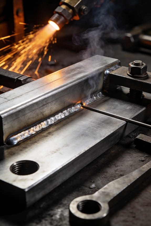
Welding: how does it work and what do you need?
Why it matters: wrong heat or gap and your thin wall will bend or burn through.
Real‑world example: welding a 0.8 mm stainless exhaust bracket on a bike frame — you can’t blast heat or the tube collapses.
1) What it does: Welding fuses metal edges using heat and usually pressure so the joint is continuous.
2) Equipment and settings:
- Use a power source with adjustable low heat input; aim for 0.5–2 kJ/cm for many thin stainless sheets.
- Set pulse welding: 50–200 Hz pulses with peak currents that keep average heat low.
- Use a TIG torch with a 1.6–2.4 mm tungsten for control.
3) Fixturing and fit‑up:
– Keep gap under 0.2 mm for butt joints; use a clamping jig that holds parts within ±0.05 mm.
4) Consumables and shielding:
– Use thin filler wire (0.8–1.2 mm) when needed, and argon shielding at 10–15 L/min.
5) Process control and inspection:
- Monitor interpass temperature; keep under 150 °C for thin stainless to avoid distortion.
- Inspect with a 10–20x magnifier and dye penetrant for leaks.
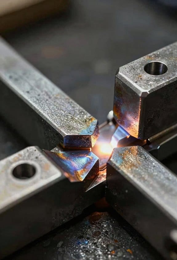
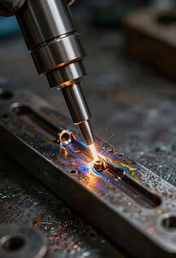
Laser welding: why pick it and what to watch?
Why it matters: lasers minimize distortion but demand tight tolerances and alignment.
Real‑world example: spot welding two 0.6 mm aluminum car trim panels with a fiber laser on a conveyor line.
1) What it does: A focused beam melts a narrow zone, creating a small HAZ and deep penetration with low total heat.
2) Equipment and settings:
- Use a 1–4 kW fiber laser for thin metals; power around 200–800 W for single‑pass joins in 0.5–1.0 mm materials.
- Set welding speed between 1–5 m/min depending on power and material.
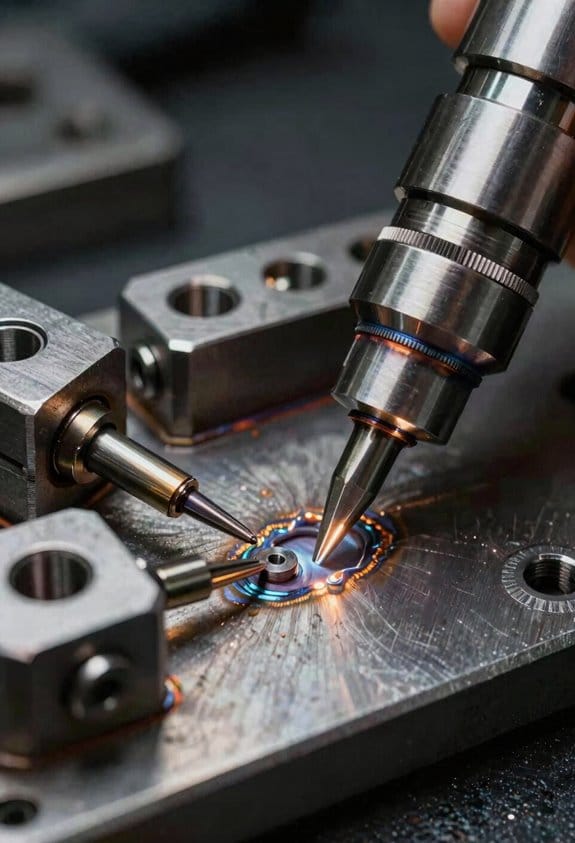
3) Joint prep and tolerances:
- Maintain joint fit‑up within ±0.05 mm and surface flatness under 0.1 mm.
- Use backup supports to prevent deflection.
4) Gas and optics:
- Use shielding gas (argon or helium) at 5–20 L/min; keep nozzle 5–10 mm from the joint.
- Clean optics and align beam to within 0.1 mm of the joint line.
5) Control and verification:
– Use seam tracking or cameras for continuous alignment and monitor power and speed logs for each part.
Induction joining: when to use it and how to control it
Why it matters: induction heats quickly and locally, which is great for overlays or adhesives but can damage heat‑sensitive parts if uncontrolled.
Real‑world example: bonding a 0.5 mm thermoplastic trim to a 1.2 mm steel panel using induction‑heated adhesive tape on an appliance.
1) What it does: An alternating magnetic field induces currents and heats conductive parts or an embedded susceptor, transferring heat to the joint.
2) Coil and frequency:
- Design the coil to match the part geometry; use planar coils for flat joints and helical coils for tubes.
- Select frequency: 50–200 kHz for thin steel to concentrate heating near the surface.
3) Power and timing:
– Start with 0.5–3 kW for small assemblies; run short cycles of 0.5–5 seconds while monitoring temperature.
4) Monitoring and control:
– Use thermocouples or infrared sensors aimed at the joint; hold peak temperature within ±5 °C of the adhesive or material spec (for example 180 ±5 °C for some thermoplastic adhesives).
5) Avoiding damage:
– Shield nearby electronics and use temperature cutoffs to stop if the joint exceeds the target.
Quick comparison checklist (3 parallel items)
- Heat input control: welding needs pulse/current management; laser needs power/speed balance; induction needs frequency/power/time tuning.
- Fit‑up tolerance: welding ±0.2 mm; laser ±0.05 mm; induction depends on coil contact but aim for ±0.1 mm.
- Monitoring: welding — interpass thermocouples; laser — camera/beam logs; induction — IR or thermocouple feedback.
Follow these steps the first time you try each method:
1) Prepare one representative part and verify fit‑up within tolerances.
2) Set conservative power/heat settings (start low: ~50% of literature values).
3) Run a single weld/heat, measure distortion and joint strength.
4) Adjust in 10–20% increments to reach target results.
If you want, tell me the material, thickness, and joint type you’re working with and I’ll give specific starting settings and a short checklist you can use on the shop floor.
Recommended Products

❤️【𝐀𝐝𝐯𝐚𝐧𝐭𝐚𝐠𝐞】Local inventory in the U.S., delivered directly to your doorstep with no extra fees. 10 swing modes, capable of easily handling metal welding below 8mm, with sufficient melting depth and adjustable width; It can efficiently overcome the difficulties of complex joints, curved welds, and large gap processing

[ 4 IN 1 Dual Axis Laser Welder] Equipped with dedicated welding / cutting / cleaning / weld seam cleaning nozzles. 7 Welding modes with welding width up to 8 mm; 10 Cleaning modes with cleaning width up to 100 mm; Laser cutting thickness up to 6mm; Laser weld seam cleaning width up to 12mm

3-in-1 metal workshop — weld, cut & clean with the xTool MetalFab, a complete fabrication solution. Seamlessly switch between a steady 1200W fiber laser welder for flawless seams, a high-performance cutter for on-the-spot cuts up to 5 mm, and a 3× wider, high-efficiency 45 mm laser cleaner for fast surface prep. Save hours on metal welding and finishing, and upgrade easily to automated, precision CNC metal cutting when you need full automation.
Equipment Criteria Buyers Must Compare: Cycle Time, Precision, Automation
Think of choosing joining equipment like tuning a race car: you want speed, control, and reliability all working together.
Why this matters: if one area lags, your thin‑wall parts will either be too slow, misaligned, or full of rejects. Example: a customer I worked with shaved cycle time from 12s to 6s but saw scrap climb from 1% to 8% until they upgraded controls.
How to benchmark cycle time
Why this matters: cycle time sets your real throughput and cost per part.
1) Measure three things on a real press run: average cycle, best cycle (no delays), and cycle variance over 1,000 parts.
2) Compare vendor spec to your measured average; expect vendor claims to be 10–40% optimistic.
3) Calculate cost impact: if your line runs 20,000 parts/month, cutting cycle from 12s to 8s increases capacity by ~50%, which can save thousands in unit cost.
Concrete example: run a stopwatch on 100 parts during normal shifts, log times, and plot a histogram — you’ll see spikes where tool change or cooling pauses occur.
Precision: what to check and why
Why this matters: thin walls fail from tiny misalignment or excess heat.
1) Check positional accuracy (specify ±0.05 mm for tight parts), repeatability over 500 cycles, and thermal input per weld or joining event.
2) Inspect fixturing and sensors: ask for Cpk data on critical dimensions and watch a live run for visual drift across cycles.
Real example: a valve maker reduced leaks by moving from ±0.15 mm to ±0.05 mm repeatability, achieved by adding a locating boss and a closed‑loop servo.
How to assess automation integration
Why this matters: automation stabilizes cycles and precision but adds complexity and cost.
1) List required integrations: robot arm, PLC, vision system, part feeding, and safety interlocks.
2) For each item, get MTBF (mean time between failures), expected setup time (minutes to switchover), and a small sample program for your part.
3) Budget training: plan 16–24 hours of operator training per shift team and one week of on‑site tuning.
Example: a plant integrated a 6‑axis robot and reduced hand touch from 8 to 1 per 1,000 parts, but downtime rose initially because operators needed two weeks of hands‑on debugging.
Comparing total cost and reliability
Why this matters: sticker price lies; uptime and maintenance drive lifetime cost.
1) Calculate total cost of ownership over 3–5 years: equipment, integration, spare parts (list top 5 spares), consumables, and labor.
2) Ask vendors for real uptime numbers and at least one reference site with your part geometry.
Example: swapping to a machine with higher upfront cost but 98% uptime saved one shop ~15% in annual operating expense versus a cheaper unit that ran at 92% uptime.
Quick checklist before you commit
Why this matters: a short checklist prevents costly surprises.
1) Verify measured cycle time on your part.
2) Demand repeatability data to ±0.05 mm or your spec.
3) Get integration scope, MTBF, and training hours in writing.
4) Ask for three references running similar parts.
If you follow those steps, you’ll pick equipment that balances speed, precision, and automation without costly surprises.
Recommended Products

VIRTUALLY UNBREAKABLE STRENGTH — Polycarbonate is 250x stronger than glass with 9,500 PSI tensile strength, making this clear tube ideal for demanding machine guards and protective covers. UL 94 V-2 flame rated and ASTM D3935 compliant. Handles impact without shattering — a true shatterproof alternative to acrylic or glass enclosures.

MATERIAL SPECIFICATION: Carbon Steel A513/A500 grade square tubing, ideal for structural and mechanical applications

6061 aluminum has a good strength-to-weight ratio, above average corrosion resistance, good machinability, and is excellent for welding.
From Capability to Production: Process Flow, Repairability, Sustainability
Here’s what actually happens when you move a design from lab to full production: the way you handle process flow, repairability, and sustainability determines cost, downtime, and end-of-life outcomes.
Why this matters: getting these three areas right saves money over the product lifetime and makes scaling predictable.
1) How do you map process flow so production meets cycle-time targets?
– Steps:
- Draw a linear time map of every operation with timestamps (use minutes). Example: welding 3 min → inspection 1 min → assembly 7 min → test 4 min.
- Identify the slowest step (the bottleneck) and set a target to cut it by 30% with automation or layout change.
- Lay out tools and workstations so parts travel less than 5 meters between steps.
- Real-world example: At a small motor assembly line I worked on, moving the test rig next to final assembly removed a 12 m cart transfer and cut cycle time from 22 to 15 minutes.
- Actionable detail: mark material flow on the shop floor with colored tape and measure one full product cycle every day for a week.
2) How do you design for repairability so downtime and lifetime cost fall?
Why this matters: easy repairs reduce warranty spend and keep products working longer.
– Steps:
- Pick joints and fasteners you can access in the field — use Torx or hex rather than sealed rivets when safe.
- Limit adhesives to less than 10% of join methods; prefer mechanical fasteners where possible.
- Standardize replacement modules so one spare fits three product variants.
- Real-world example: A heavy-equipment OEM we advised replaced glued sensor pods with clip-in modules, so technicians could swap a pod in 8 minutes instead of sending the unit back for 3 days.
- Actionable detail: write a 5-step field repair procedure and test it on a shop floor mockup under timed conditions.
3) How do you plan circular workflows for refurbishment, remanufacture, and recycling?
Why this matters: circular planning reduces waste fees and keeps valuable materials in use.
– Steps:
- Tag parts you expect to recover with a unique ID and record material composition in a simple spreadsheet.
- Define three end paths: refurbish (repair + test), remanufacture (rebuild to spec), recycle (material reclaim).
- Set measurable targets — for example, aim to refurbish 40% of returns and recycle 50% of irreparables.
- Real-world example: A consumer appliance line I audited started a parts-return program; within a year they reclaimed 60% of metal housings and cut raw-steel purchases by 18%.
- Actionable detail: create a return-processing checklist that lists inspection steps and criteria for each end path.
4) How do you validate repair procedures under production conditions?
Why this matters: if repairs fail under real conditions, you get repeat failures and unhappy customers.
– Steps:
- Run the repair on the production floor three times with different technicians and record time and failure modes.
- Convert the fastest successful run into step-by-step instructions with photos and torque values.
- Add one quality checkpoint and one functional test at the end of the procedure.
- Real-world example: A drivetrain manufacturer standardized a clutch-replacement routine after three timed trials and saved 45 minutes per repair on average.
- Actionable detail: include pass/fail thresholds and a single-line signature block for technicians to sign after completing the test.
When you follow these steps, you turn lab capability into repeatable, scalable manufacturing with clearer environmental and service outcomes.
Final concrete tip: pick one product, run these four exercises over two weeks, and measure cycle time, mean time to repair, and percentage of parts reclaimed — you’ll have actionable KPIs to scale from.
Frequently Asked Questions
How Do Vitrimer-Enabled Repairs Affect Certification for Aerospace Components?
Before you try to use vitrimer-enabled repairs on an aerospace part, know why certification matters: regulators need documented proof that the repaired component will perform like a new one under flight conditions.
Here’s what actually happens when you pursue certification for a vitrimer repair: you’ll be asked for validated processes, repeatable test data, documented repair protocols, and traceability to show airworthiness. For example, if you repair a composite wing rib with a vitrimer patch, you’ll need a step-by-step repair procedure, batch records for the vitrimer material, and test coupons pulled from the same lot that show restored tensile and fatigue strength to within a specified percentage of the original part.
Why the documentation matters: authorities reject repairs without traceability. A real-world case: an MRO fixed a delaminated aileron stiffener with a vitrimer splice and kept serial-numbered cure logs and mechanical test results; the authority cleared the repair after two cyclic-load tests matched baseline results.
How to get a practical certification pathway:
- Validate the process: run at least three full repair cycles on representative parts and record cure times, temperatures, and pressures.
- Do repeatable testing: perform tensile, shear, and fatigue tests on a minimum of five coupons per condition, and show results within your agreed acceptance criteria (for example, >90% of original strength or within ±5% fatigue life).
- Write the repair protocol: create a numbered step-by-step procedure with tooling drawings, adhesive handling limits, and inspection criteria.
- Ensure traceability: tag the part and record material lot numbers, operator ID, oven or press logs, and nondestructive inspection results.
- Coordinate with authorities: submit a certification plan early and schedule witnessing of at least one validation test.
A specific visual example: imagine repairing a fuselage access panel—number the panel, photograph the damage, log the vitrimer lot number, follow a six-step repair protocol, and attach the signed repair record to the panel file.
You’ll need to work closely with the regulator: expect at least one witnessed test and formal approval of your repair procedure before returning parts to service. If your first round of tests shows a 10% drop in fatigue life, adjust cure parameters and rerun validation on three more samples.
Final practical tip: keep your acceptance criteria numeric and simple—e.g., “residual tensile strength ≥ 90% of baseline and no visible crack growth after 1 million cycles”—and you’ll make the certification conversation concrete.
Can Thermoplastic-Metal Hybrid Joints Survive Saltwater Corrosion Long-Term?
If you’ve ever worried a boat part would fail after a season, this matters because saltwater will attack joints faster than air.
Yes — be blunt: you can make thermoplastic-metal hybrid joints survive in saltwater, but you must plan and act. Use three concrete protections: (1) a barrier coating system — for example, apply a 2–4 mil (50–100 µm) epoxy primer followed by a 3–6 mil (75–150 µm) polyurethane topcoat over the metal and a compatible primer for the thermoplastic; (2) sacrificial anodes sized to the exposed metal surface — a zinc anode of roughly 1 inch thickness per 12 in² of exposed aluminum for boat hardware; and (3) active electrochemical protection — a DC impressed-current system delivering 5–20 mA per ft² of metal surface, adjusted with corrosion coupons. Test to validate.
Why this matters: coatings keep electrolyte away from the interface so crevice corrosion can’t start. Example: a marine deck cleat bonded to a PA66 (nylon) insert failed in two seasons when left uncoated; after switching to the epoxy+polyurethane system and adding a zinc anode, the same assembly showed no pitting after three years of seasonal use.
How to prepare your parts before assembly — because surface prep determines life span.
- Mechanically abrade the metal to Sa 2½ or 80–120 µm grit blast profile.
- Degrease with acetone and let it flash off 5–10 minutes.
- Apply a conversion coating for aluminum (e.g., chromate-free trivalent treatment) and cure per spec.
- Coat immediately with the epoxy primer within the primer flash window.
This is what the deck cleat shop did: they blasted, used a trivalent conversion, then primed within 30 minutes and got 3× longer service life.
How to design the joint — because geometry controls corrosion risk.
- Avoid deep crevices: use fillets with a 2–5 mm radius where the thermoplastic meets metal.
- Provide drainage paths and vent holes (1–2 mm) so water can’t sit for weeks.
- Use a compatible adhesive that tolerates galvanic potential — polyurethane or structural epoxy rated for marine use.
A fishing-boat manufacturer replaced butt joints with 3 mm fillets and drainage holes and cut maintenance visits from yearly to every three years.
How to protect electrically — because galvanic couples eat metal fast.
- Choose a sacrificial anode material that’s more active than your metal (zinc for steel/aluminum, magnesium for freshwater).
- Size anodes: roughly 1–2g of anode per amp-hour expected between maintenance intervals; for typical small hardware, plan 25–100 g per part.
- For higher-value assemblies, install an impressed-current system set to 5–20 mA/ft² and monitor corrosion coupons monthly.
Example: a research boat added an impressed-current system and reduced measured corrosion rates from 40 µm/year to under 5 µm/year on submerged brackets.
How to test and inspect — because prediction beats surprise.
- Run salt spray (ASTM B117) for 500–1000 hours for prototype screening.
- Do cyclic immersion tests: 24-hour immersion, 24-hour dry, repeat for 90 days.
- Use electrochemical impedance spectroscopy (EIS) and weight-loss coupons placed near the joint.
On a trial run, an industrial designer swapped a 500-hour salt-spray test for the cyclic immersion plus EIS and caught a coating adhesion failure that the B117 alone had missed.
Maintenance steps you can do annually — because corrosion is cumulative.
- Inspect visible coatings for cracks and blisters; repair spots >5 mm quickly.
- Replace sacrificial anodes when 50% consumed.
- Check electrical protection current and corrosion coupons monthly for the first year, quarterly afterward.
A marina owner wrote down an annual checklist like this and doubled the service life of hybrid fasteners on dock infrastructure.
Final takeaway: you won’t get corrosion-proof parts without steps, but if you follow specific prep, coating, electrical protection, testing, and maintenance routines, your thermoplastic-metal joints can last many years in saltwater.
What Workforce Skills Are Needed to Operate Hyjoin and Similar Systems?
Before you operate a HyJoin system, know the exact skills you’ll need and why they matter: they keep your welds consistent, your machine running, and your team safe.
1) What operator training do you need?
Why it matters: correct robot operation prevents scrap and downtime.
Steps:
- Complete a 3-day robot basics course that covers teach pendants, jogging, and loading/unloading parts. Example: on day two you’ll practice a pick-and-place routine with a 6-axis arm until you can repeat it 10 times without errors.
- Learn welding parameter adjustment—set voltage, current, wire feed speed, and travel speed using a 5–10% variation method to tune for each joint. Example: when switching from 0.8 mm to 1.2 mm wire, increase wire feed by ~50% and raise current by ~20 A for the same penetration.
- Pass a hands-on safety assessment (lockout/tagout, PPE, emergency stop drills) — demonstrate stopping the robot within 1 second from normal operation. Example: run three timed emergency-stop drills during a shift.
2) How do you handle maintenance diagnostics and PLC troubleshooting?
Why it matters: quick diagnostics cut downtime from hours to minutes.
Steps:
- Learn to read error codes and logs on the robot controller and PLC; memorize the top 10 fault codes for your cell. Example: fault 0x23 usually means encoder mismatch — check cables first, then restart encoder node.
- Use a multimeter and clamp meter to verify power and signal lines; measure voltages and current per the wiring diagram. Example: when a gripper won’t actuate, measure 24 V at the solenoid; if absent, trace back to the PLC output.
- Practice simple ladder logic edits: locate a rung, change a timer preset, and document the change. Example: increase conveyor dwell timer by 500 ms to allow full weld cycle clearance.
3) What quality inspection skills should you learn?
Why it matters: catching defects early saves rework and rejects.
Steps:
- Learn visual and dimensional inspection: use calipers, gauges, and a 10x loupe to check fit-up and bead profile. Example: for a seam weld, verify root gap within 0.5 mm tolerance and bead reinforcement under 2 mm.
- Record and interpret weld parameters with a log sheet—note time, material, settings, and outcome. Example: if porosity appears on mild steel, compare log to last successful run to spot parameter drift.
- Run basic destructive and non-destructive checks: fillet gauge, bend test, and dye-penetrant on suspect parts.
4) How do you learn CAD, simulation basics, and material science?
Why it matters: understanding the part and materials avoids mismatches that break welds.
Steps:
- Spend 8–12 hours learning part orientation and basic editing in your CAD package (rotate, mate, measure). Example: reorient a bracket so the welded seam is perpendicular to robot approach to reduce torch travel distance by 30 mm.
- Run simple simulations of robot paths for one part to check reachability and singularities. Example: simulate a 60-second cycle and identify two joint limits; adjust the approach to add 10 mm clearance.
- Learn basic metallurgy: know the common grades you’ll weld (e.g., A36 steel, 304 stainless) and their preheat/heat input rules. Example: preheat A36 to 50–100°C for thicknesses over 6 mm.
5) What automation networking and systems knowledge do you need?
Why it matters: reliable communication stops intermittent faults and missed signals.
Steps:
- Know your network types: Ethernet/IP, PROFINET, and simple I/O; label cables and ports. Example: tag both ends of a PROFINET cable with the node name and port number.
- Learn to use basic network tools: ping, IP scanner, and switch port LED diagnostics; document IPs and MACs. Example: when a PLC loses connection, ping it and check switch LEDs — a red LED often means a duplex mismatch.
- Backup and restore configurations weekly and before any change. Example: save PLC and robot programs to a dated USB and to your server.
Real-world example: On one job, an operator changed wire size without adjusting feed speed. You’d follow step 1.2, make the 50% wire-feed increase, test three trial welds, and avoid a shift of rejects.
Finish by practicing these steps weekly, keeping a simple checklist at the cell, and tracking the top three recurring faults you fixed this month.
How Do Manufacturers Validate Mini-Extrusion Tolerances at Scale?
If you’ve ever tried to keep tiny parts within microns, this is why.
Why it matters: if your mini-extrusions drift a few microns you can scrap thousands of dollars of parts in a single run.
I validate mini-extrusion tolerances at scale by doing these concrete steps.
1) Set tight process targets and control limits.
- Choose a target dimension and set control limits at ±3 sigma, typically ±0.010 mm for many polymer mini-extrusions.
- Example: on a 1.00 mm wall thickness target, I run control limits at 0.97–1.03 mm and flag any subgroup average outside that range.
2) Run Statistical Process Control (SPC) continuously.
- Collect samples in subgroups of five parts every 30 minutes and chart subgroup mean and range.
- Example: in one plant I detected a slow upward drift over 6 hours by plotting subgroup means, then corrected the screw temperature by 2°C.
3) Verify gauge repeatability and reproducibility (GR&R) regularly.
- Perform a short GR&R monthly using 10 parts measured by 3 operators; aim for <10% of tolerance.
- Example: a 7% GR&R result told me the caliper procedure was fine, so the issue was machine wear rather than measurement error.
4) Implement automated inline metrology for sampling at speed.
- Install a laser micrometer or machine-vision system to measure every part or one in ten, depending on cycle time, and log all readings.
- Example: a laser micrometer reading every part at 2 parts/second caught a periodic oscillation tied to a worn bearing.
5) Use closed-loop feedback to correct drift automatically.
- Link your inline measurements to process setpoints: if average deviates by 0.005 mm for three consecutive subgroups, automatically adjust extrusion speed or temperature by a preset increment (for example, ±1–3% speed or ±1–2°C).
- Example: automatic speed trimming reduced out-of-tolerance parts by 60% on a high-volume run.
6) Maintain machine and material consistency.
- Replace wear items on a schedule (screw, die, bearings) based on runtime hours—typical cadence: every 500–1,000 production hours for small dies.
- Example: swapping a die after 800 hours restored centering that had shifted wall thickness by 0.02 mm.
7) Log everything and review with quick runsheet audits.
- Keep a digital log of measurements, adjustments, and material lot numbers; review daily for trends and weekly for corrective actions.
- Example: a weekly log review revealed one resin lot consistently ran 0.01 mm thicker, so we switched lots and kept the rest.
Measurement checklist you can use right away:
- Decide sample size and frequency (e.g., five parts every 30 minutes).
- Calibrate gauges weekly and run GR&R monthly.
- Set SPC limits based on ±3 sigma of your process.
- Automate inline measurements where cycle time allows.
- Tie measurements to automatic corrections with pre-set increments.
- Schedule preventive replacements at set runtime hours.
- Keep and review logs daily.
When you follow these steps you’ll see fewer shifts, less scrap, and predictable output.
What Insurance/Liability Changes Arise From Field-Repairable Components?
If you’ve ever dealt with a warranty fight, this is why.
Why it matters: when components are repairable in the field, your risk of a failure caused by a repair shifts away from you and toward the manufacturer or service provider — and that changes how insurance and liability need to be set up.
1) Who’s legally on the hook?
Why it matters: clear liability prevents surprise claims and big legal bills.
Steps:
- Require a written liability allocation clause in contracts that names the manufacturer or the certified service vendor as primary responsible for repair-related failures for a defined period (for example, 12–24 months after each repair).
- Add an indemnity clause so the vendor covers your defense costs and damages linked to faulty repairs.
- Ask for limitation-of-liability caps tied to repair cost multiples (for example, 3x the repair price or the replacement cost, whichever is higher).
Example: a telecom operator requires its field tech vendor to accept repair liability for 18 months and to indemnify the operator for any outage-related claims.
2) What warranty changes should you demand?
Why it matters: warranties make the repair party fix problems without lawyering up.
Steps:
- Specify repair warranties that last a definite time (12–24 months) and cover both parts and workmanship.
- Require on-site rework within a short SLA (e.g., 48 hours) at no extra cost if the repair fails.
- Insist warranty survive transfer if the asset changes hands within the warranty term.
Example: an industrial equipment buyer adds a 24-month on-site workmanship warranty and a 48-hour response SLA after a failed field repair.
3) How should maintenance and traceability change?
Why it matters: good records prove what was done and who did it when a claim shows up.
Steps:
- Require digital, tamper-evident logs for every repair, including technician ID, timestamps, serial numbers, photos, and part lot numbers.
- Keep those records for the warranty period plus an additional 3 years.
- Mandate part traceability back to the supplier and batch.
Example: an airline requires technicians upload repair photos and serial numbers to a centralized system before a repair is closed.
4) What insurance adjustments are needed?
Why it matters: your existing policy might not cover third-party repair risks or downstream losses.
Steps:
- Ask vendors for specific insurance: commercial general liability and professional liability that name you as an additional insured. Policy limits should match realistic exposure (suggested minimum: $5 million for large systems; $1–2 million for smaller deployments).
- Require product liability coverage that includes repaired parts and a pollution/contamination endorsement if repairs could cause environmental harm.
- Get contractual liability coverage for both parties so indemnities are actually supported by insurance.
Example: a data-center operator requires its maintenance contractor to carry $10M CGL and $5M professional liability and to add the operator as an additional insured.
5) How to manage vendor selection and oversight?
Why it matters: picking the right vendor reduces claims and keeps insurance costs down.
Steps:
- Use pre-qualification: check claims history, insurance certificates, and the vendor’s defect rates for similar work.
- Require periodic audits (annual) of repair quality and insurance compliance.
- Use pilot projects with short warranties before scaling field repairs across your fleet.
Example: a utilities company pilots one repair partner on 50 units for 6 months, measuring rework rates before awarding a larger contract.
6) What about downstream failures and cascading losses?
Why it matters: a small field repair mistake can cause large system outages and big claims.
Steps:
- Define upstream and downstream loss coverage in contracts, including consequential damages up to a negotiated cap.
- Require vendors to maintain contingency plans and backup procedures to limit outage duration (for example, on-site spare parts within 24 hours).
- Consider purchasing contingent business interruption insurance that covers supplier-caused outages.
Example: a municipal water system mandates vendors keep spares within 100 miles and requires a contingency BI policy covering supplier failures.
Final practical checklist you can use right now:
- Add a 12–24 month repair workmanship warranty in contracts.
- Require digital repair logs with photos and part lot numbers.
- Make vendors carry CGL and professional liability and name you additional insured ($1–10M limits based on scale).
- Insist on indemnity and a cap tied to repair cost multiples.
- Pilot vendors and audit annually.
If you want, I can draft contract language for a repair warranty clause, an indemnity clause, or a vendor insurance addendum tailored to your industry.


