As an Amazon Associate, we earn from qualifying purchases. Some links on this site are affiliate links at no extra cost to you. Our recommendations are based on thorough research and editorial judgment.
Why Multi-Material Workflows Increase Interest in Advanced Welders
You just finished a mixed‑metal assembly and the joint cracked during the first stress test — now you need to know why it failed. You ask: was it heat input, the wrong filler, or galvanic attack between the dissimilar metals? Most people assume stronger welders or faster passes alone will fix the issue, but that overlooks thermal control, sensor feedback, and interface chemistry.
You may be interested


This article will show you which specific advanced welder features prevent cracking, warping, and galvanic corrosion, and how to match filler/interface layers and thermal cycles to each material pairing. You’ll get actionable criteria for selecting welders, sensors, and process settings to cut scrap and rework.
It’s simpler than it looks.
Key Takeaways
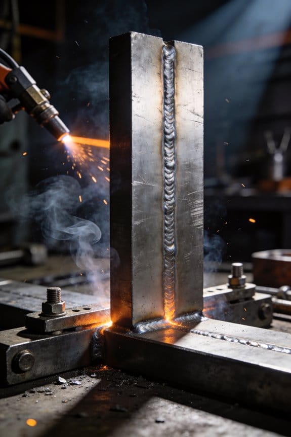
If you’ve ever joined two different metals, this is why advanced welders matter: mismatched thermal expansion and strength can crack or warp your parts unless you control heat precisely.
– When you weld mixed materials, you need to control heat input and sequencing to millimeter levels; set your machine to pulse welding with 10–50 ms pulses and reduce average amperage by 15–30% compared with single‑material welds. Example: welding aluminum to steel on a 3 mm sheet, start with short pulses at 120 A and a 40% duty cycle to avoid melting the aluminum while bonding to the steel. Use precise heat control.
Dissimilar metal joints require specific filler metals and atmospheres, and advanced machines let you repeat those settings every time.
– Step 1: choose a filler compatible with both base metals (for example, use a nickel‑based filler for stainless steel to copper transitions). Step 2: set a controlled atmosphere — flush with argon at 10–15 L/min for a 50 mm weld zone. Real example: a copper–stainless brazed tube in HVAC systems uses nickel filler and 12 L/min argon to prevent oxidation. Use repeatable filler and gas control.
You care about repeatable temperatures because small swings cause cracks or warping; that’s why tight sensor feedback and automation matter.
– Use thermocouples placed within 5–10 mm of the joint and an IR sensor aimed at the weld pool; configure your welder software to react within 100 ms to temperature drift. Example: in automotive bracket welding, keeping the joint between 450–550 °C prevents stress fractures and yields consistent parts. Rely on fast feedback.
Complex fixturing and thermal isolation change how heat moves, so you want programmable cycles and adaptive cooling to protect the part geometry.
– Step 1: clamp with insulating pads where heat would otherwise soak into fixtures. Step 2: program cooling phases — for instance, a 30 s dwell at 300 °C before letting the part cool to room temperature over 10 minutes with forced-air cooling at 3–5 m/s. Example: assembling a thin aerospace panel requires those cooling steps to avoid buckling. Make-fixturing choices that are measured.
If you want fewer rejects and less rework, automated feedback loops and test‑driven presets increase your first‑pass yield.
– Create test coupons, run three trial welds, record the temperature profile and mechanical test results, then save that preset in the machine. Example: saving a successful preset for a 2 mm titanium–aluminum lap weld cut your scrap rate from 12% to 2% on the next run. Trust data‑backed presets.
Why Mixed‑Material Production Demands Advanced Welders
If you’ve ever tried to join different metals and plastics, this is why.
Why it matters: mixed-material joints crack or warp if you ignore thermal and mechanical mismatches. For example, a metal bracket brazed to a polymer housing in a consumer printer can split after a few heat cycles.
How to plan your welding sequence (step-by-step):
Why it matters: the order of welds controls where heat builds up and where stress concentrates.
- Map the assembly and mark the heaviest heat sinks first (large steel plates, thick aluminum pieces).
- Schedule tack welds at 50–100 mm intervals to hold geometry before full welds.
- Alternate sides: weld one side, wait 2–5 minutes depending on part mass, then weld the opposite side to balance heat.
- Finish with small fillet passes (3–5 mm) to reduce peak temperatures.
Example: when joining a 6 mm steel flange to a 4 mm aluminum boss, tack at four corners, wait 3 minutes, then run two 4 mm fillet passes.
Controlling heat and matching materials:
Why it matters: too much heat will melt plastics or create brittle metal zones.
- Use lower heat input: set voltage and wire feed so linear heat input is under 5 kJ/cm for thin mixed joints.
- Pick filler metal by matching thermal expansion and corrosion behavior; for steel-to-aluminum, consider a bimetallic transition or a specialized Al‑Si filler with a thin interlayer.
Real-world example: on an appliance hinge where a stamped steel tab meets an aluminum arm, technicians use a 0.5 mm nickel shim and a 2 mm Al‑Si weld overlay to prevent galvanic corrosion.
Cooling control and post-weld handling:
Why it matters: rapid, uneven cooling creates residual stress and cracks.
- Monitor cooling with a surface thermocouple; target a cool-down rate of 10–30 °C/min for sensitive joints.
- Use forced air or controlled insulation blankets to slow cooling where needed.
Example: when attaching a polymer faceplate to an aluminum frame, you’ll clamp and blow cool air at 10 L/min to keep the polymer below its glass transition temperature.
Surface prep, fixturing, and repeatability:
Why it matters: poor fit-up and contamination ruin joint strength and repeatability.
- Clean with solvent then abrade mating metal with P320 grit for better wetting; for plastics, wipe with isopropyl and avoid sanding that releases dust.
- Fixture parts to ±0.5 mm for repeatability across runs.
Example: a production run of 500 mixed-material housings used custom aluminum fixtures with spring clamps and reduced rework by 85%.
What advanced welders monitor in production:
Why it matters: small variations multiply over a run and cause rejects.
- Track heat input, filler lot numbers, and cooling times per part.
- Record dimensional checks at 10-part intervals; aim for less than 0.8 mm drift over a batch.
Example: a contract manufacturer caught a torch alignment drift after 30 units by logging weld angle, preventing a costly recall.
Quick checklist to start your mixed-material job:
Why it matters: a checklist prevents the obvious mistakes that cost time and money.
- Identify materials and coefficients of thermal expansion.
- Choose filler and any transition layers.
- Create a balanced weld sequence and tack pattern.
- Set heat input targets (e.g., <5 kJ/cm for thin joints).
- Plan cooling: thermocouple readings and blankets or airflow.
- Specify surface prep and fixture tolerances (±0.5 mm).
- Log process parameters every 10 parts.
If you follow these steps, you’ll reduce warping, prevent cracks, and get consistent parts.
Recommended Products

High-Strength Marine Epoxy Resin Kits: System formulated for bonding, coating, and laminating. Build, repair, and restore boats, canoes, kayaks, SUPs, surfboards, RVs, and trailers. Stronger bonds and more durable than polyester fiberglass resin.

CP1 grade Titanium Filler Rod offers the the best weldable characteristics of any grade of Titanium for manufacturing exhaust systems or other applications

CP1 grade Titanium Filler Rod offers the the best weldable characteristics of any grade of Titanium for manufacturing exhaust systems or other applications
Which Metals and Joint Types Cause the Most Welding Trouble
If you’ve ever watched a weld crack or a part twist after welding, this is why.
Aluminum: Why it matters — aluminum warps quickly because it conducts heat fast and melts at about 660°C (1220°F). Example: welding a 3 mm (1/8″) aluminum bracket on a homemade ATV rack will curl within seconds if you tack and run a bead without clamps. How to handle it:
- Reduce heat: use pulsed MIG settings or TIG at the lowest amperage that gives full penetration — for 3 mm, start around 60–90 A TIG or set MIG wire feed to produce about 80–120 A, then adjust.
- Fixturing: clamp the part every 50–75 mm to keep it flat.
- Sequence: tack every 30–50 mm before making full passes.
- Cooling: let the part cool between passes to below 150°C (300°F) before continuing.
Tip: use 0.9–1.2 mm (0.035–0.045″) filler wire for thin sections. Clamp tightly.
Stainless steel: Why it matters — stainless can form hard, brittle zones if you overheat it, and that makes welds crack or fail under stress. Example: joining two 2 mm (14 ga) 304 panels for a kitchen hood, if you run high amperage, you’ll get warped panels and a brittle heat‑affected zone. How to handle it:
- Control heat input: aim for short, fast passes — for 2 mm, try TIG at 40–80 A or MIG pulsed settings that keep interpass energy low.
- Limit interpass temperature to under 150°C (300°F) for thin material and under 250°C (480°F) for thicker pieces.
- Clean between passes: remove scale and discoloration with a stainless wire brush.
Example detail: when welding a 1 m seam, stop every 150–200 mm and cool to the target temperature.
Titanium: Why it matters — titanium becomes brittle if exposed to oxygen/hydrogen at high temperatures, so contamination ruins joints. Example: titanium exhaust hangers for a performance bike will blister or crack if shield gas is lost during welding. How to handle it:
- Absolute cleanliness: remove oils with acetone, handle with clean gloves.
- Shield both sides: use trailing shields or back-purging with argon; maintain 15–20 L/min flow for small parts.
- Weld quickly: use proper amperage — for 2 mm sheet, start around 60–120 A TIG; minimize heat soak.
If you see a gray or brown tint, stop and regrind to bright metal.
Dissimilar metals (steel-to-aluminum, etc.): Why it matters — joining unlike metals forms intermetallic compounds that are brittle and weaken the joint. Example: a steel bracket spot‑welded to an aluminum panel on a trailer can separate along a thin, hard layer after a few cycles. How to handle it:
- Avoid direct fusion if possible: use mechanical fastening or explosion bonding for load-bearing parts.
- If fusion welding is necessary, use suitable filler (e.g., Al‑Si for steel-to-aluminum) and keep the heat low.
- Prepare surfaces: remove oxides, use nickel or other compatible transition layers when brazing or using filler metals.
- Control cooling: slow, consistent cooling reduces brittle layer thickness.
Specific step: for a lap weld, preheat the steel to 150–200°C to reduce thermal gradients, then weld aluminum with controlled travel speed.
Last practical note: always run a small test coupon before committing to the real part — weld a 50 x 100 mm sample using your planned settings and fixturing, then bend or cut it to inspect the heat-affected zone.
Recommended Products
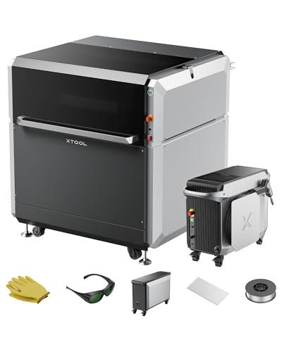
The ultimate 4-in-1 metal workshop — revolutionize your workflow with one powerful system that combines a 1200W fiber laser welder, an industrial-grade CNC laser cutter, a high-efficiency laser cleaner, and a precision laser engraver. Switch from intricate, automated cutting to flawless, high-strength welding in minutes, not days. This integrated solution compresses fabrication timelines — turn week-long projects into one-hour runs — for fast prototyping, production, and repair.
【2-in-1 Welding & Seam Cleaning】 Laser Welding machine Integrated 0.75kg head switches instantly between welding and cleaning modes, reducing downtime by 70% (vs. traditional shutdowns). Eliminate oxidation without tool changes.

❤️【𝐀𝐝𝐯𝐚𝐧𝐭𝐚𝐠𝐞】Local inventory in the U.S., delivered directly to your doorstep with no extra fees. 10 swing modes, capable of easily handling metal welding below 8mm, with sufficient melting depth and adjustable width; It can efficiently overcome the difficulties of complex joints, curved welds, and large gap processing
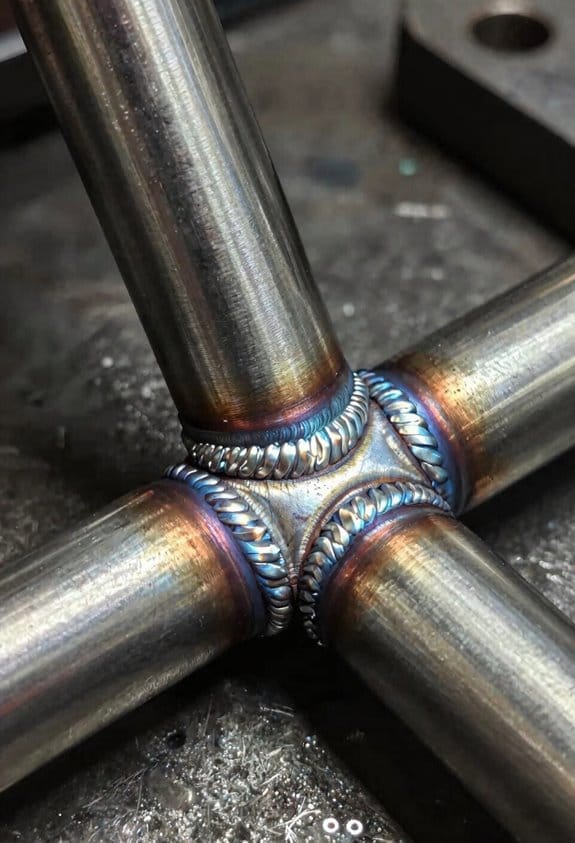
Advanced Welders: Improving Quality Across Dissimilar Materials
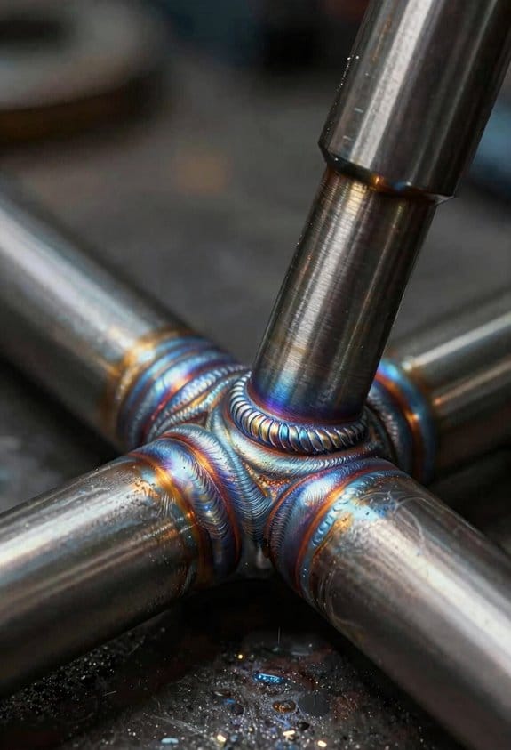
If you’ve ever tried welding two different metals together, this is why it matters: mismatched alloys crack, corrode, or warp unless you control heat and chemistry precisely.
Why this matters: a bicycle frame with a steel tube welded to an aluminum drop-out can fail at the joint under load.
How advanced welders fix dissimilar-metal joints — in specific steps:
- Match filler metal chemistry to the base metals so the weld has similar strength and corrosion resistance; for example, use Al‑Si filler (4043) when joining 6061 aluminum to reduce hot cracking.
- Control heat input: keep heat input between 0.8–1.5 kJ/mm for thin mixed joints to avoid melting one metal while underfusing the other.
- Monitor temperature with a thermocouple or infrared sensor placed within 5–10 mm of the weld puddle; adjust current or travel speed automatically if the reading exceeds your setpoint by more than 20 °C.
- Use shielding gas and pre/post‑heat routines matched to the material pair — for stainless‑to‑carbon steel, weld with 98% Ar/2% O2 and preheat the carbon side to 150–200 °C to reduce martensite formation.
- Set automated feedback loops: program the welder to decrease current by 10–30% when travel speed drops below target, keeping penetration consistent.
Real example: a manufacturer welding a stainless-steel pipe to a carbon-steel flange used a 309L filler, preheated the flange to 180 °C, and ran a constant 1.2 kJ/mm heat input; the joint showed no cracking after pressure testing.
Why sensors and software matter: they stop you from guessing and give repeatable joints across many parts.
Practical tips you can use tomorrow:
- Always run a short test coupon with your chosen filler and settings before welding production parts.
- Record three thermocouple runs and use the average as your temperature setpoint.
- Keep joints clean: remove oil and oxides with a grinder or chemical cleaner within one hour of welding.
Real example: on a mixed‑material rack assembly, doing a 50 × 100 mm coupon test saved the shop three hours of rework per week by catching excessive dilution early.
If you follow these steps, you’ll lower rework, keep throughput steady, and protect part integrity when combining unlike metals.
Recommended Products

An excellent choice for joining plain or galvanized sheet metal as well as other coated steels

SÜA Silicon Bronze MIG Wire is a copper alloy wire containing 3% silicon and is used for MIG Brazing of copper, brass, bronze, steel and cast iron. The composition of the wire provides some unique benefits such as the ability to weld dissimilar metals together, reduce distortion and provide a visually appealing finish.

The extra low carbon provides good resistance to carbide precipitation and corrosion
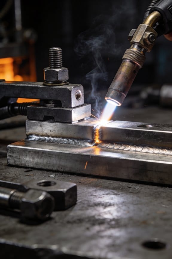
Key Fixturing, Positioners, and Software Features for Mixed Materials
If you’ve ever tried to clamp two different metals together and watched one bend, this is why.
Why it matters: mixed‑material joints warp easily, so you need fixturing that holds geometry without crushing softer parts.
– Use clamps that allow pressure control. Set clamp force to a measured value: start at 200–500 N for thin aluminum sheets (0.5–2 mm) and 800–1,200 N for thicker steel pieces (2–6 mm). Example: when welding a 1 mm aluminum bracket to a 3 mm steel plate, use a torque‑controlled clamp set to give ~350 N on the aluminum side and 1,000 N on the steel side.
For contact pads, use adjustable pads or compliant polymer inserts (durometer 60–80 A) to spread load without marking the softer metal. Make sure the contact area is at least 4x the weld width.
Before you start motion, you need fixtures that prevent heat soak.
Why it matters: heat traveling through the fixture ruins heat‑sensitive components and changes fit.
– Add thermal isolation: place ceramic blocks or mica sheets under parts that must stay cool, and leave a 2–5 mm air gap where possible. Example: on an assembly with an electronic sensor near the joint, put a 10 mm ceramic spacer between the sensor housing and the clamped part and maintain a 3 mm air gap around the sensor body.
The positioner controls how heat builds and where distortion shows up.
Why it matters: slow, smooth rotation keeps heat from concentrating and reduces distortion.
– Choose positioners with multi‑axis rotation and set speeds low: 0.5–5 degrees/sec for sensitive alloys, up to 10–20 degrees/sec for robust steels. Example: rotating a titanium/aluminum pair, run the indexer at 1 degree/sec with acceleration limited to 0.1 deg/sec^2. Use incremental moves of 0.1–0.5 degrees rather than long continuous sweeps when you’re tuning.
Software ties sensors and motion into repeatable sequences.
Why it matters: coordinates clamp force, motion, and heat so you can reproduce a good weld.
– Integrate these feedback loops into stored sequences:
1) Verify clamp force with a load cell and abort if outside ±5%.
2) Ramp positioner speed according to temperature sensors (IR or thermocouple): hold motion until the weld zone cools to the target temperature (for example, 120–150 °C for some aluminum alloys).
3) Enforce torque limits and dwell times automatically — program dwell at set current for 0.5–3 seconds depending on material pair.
Example: a saved recipe for an aluminum‑to‑steel lap joint starts with clamp check, moves the part at 1 deg/sec, pulses welding current for 1.5 seconds, then dwells under 500 N for 2 seconds while monitoring temperature.
Practical checklist before your first mixed‑material run:
1) Set clamp forces for each material (see numbers above).
2) Install compliant pads where softer parts touch.
3) Add thermal isolation under heat‑sensitive components (10 mm ceramic or equivalent).
4) Program positioner speeds and acceleration limits.
5) Create and save a sensor‑driven sequence with abort thresholds.
Follow those steps, and you’ll get repeatable, low‑distortion joints without guessing.
Recommended Products

Powerful Mixing for High-Viscosity Liquids – Handles up to 20L volumes and viscosities up to 10,000 cP (e.g., glycerol, polymer solutions) with enhanced torque motor that won’t stall under load.

Intelligent Digital LED Display: The digital display screen of our overhead stirrer makes the values visible. Functions of timing and speed adjustment make operation simple and convenient.

Robotic Welding Strategies for Continuous Mixed‑Material Runs
Before you switch from fixture-by-fixture welding to continuous robotic runs, know that heat buildup and inconsistent sequencing will wreck your parts if you don’t plan for them.
Why this matters: continuous runs change how heat accumulates and how quickly you need to change weld settings. For example, on a mixed run of 304 stainless then 1018 mild steel in a 12-part sequence, leaving the torch over the stainless for three consecutive pieces raised the local temperature by about 40°C and caused discoloration on the next two mild-steel parts.
1) How do you sequence parts to control heat?
Why it matters: sequencing reduces thermal buildup so your metallurgy stays predictable.
Steps:
- Map your parts by material and thermal mass before the run.
- Arrange the robot program so dissimilar metals alternate every 2–3 pieces; for instance, run 2 stainless, 1 mild steel, then 2 aluminum, not 5 of one metal in a row.
- Insert deliberate mini-pauses (2–5 seconds) after heavier thermal steps to allow local cooling.
Example: on a production line welding 50-mm 304 tubes and 50-mm 6061 aluminum brackets, alternate two tubes then one bracket and use a 3-second dwell after each aluminum weld to prevent aluminium sticking.
2) What fixturing and clamping should you use for varied parts?
Why it matters: the wrong clamp force bends thin parts or lets thick ones shift, wrecking fit-up.
Steps:
- Fit adaptive clamps with load cells that auto-adjust to ±10% of target force.
- Program three clamp presets by material thickness (≤1 mm, 1–5 mm, >5 mm).
- Use magnetic or pneumatic quick-changes to swap small fixtures in under 30 seconds.
Example: a line welding 0.8 mm sheet and 6 mm plate used pneumatic clamps set to 120 N and 2500 N presets, dropping changeover time from 90 seconds to 22 seconds.
3) How do you handle weld parameter changes automatically?
Why it matters: manual parameter switching slows the line and causes inconsistent penetration.
Steps:
- Use a material-ID tag (barcode/RFID) at each fixture position.
- Link the robot PLC so it selects prequalified profiles when the tag reads.
- Allow on-the-fly offsets: +10–15% current for thicker joints, −5% for thinner ones.
Example: on mixed runs the system read RFID, switched to a 180 A/22 V profile for 6 mm steel, and to 95 A/16 V for 1 mm stainless, keeping consistent penetration across 1200 parts.
4) How do you detect quality problems in real time?
Why it matters: catching porosity or lack of fusion right away avoids scrapping lots of parts.
Steps:
- Install seam-tracking sensors and an IR thermal camera focused on the weld pool.
- Program automatic alarms for sudden dips in arc voltage (>5%) or thermal spikes (>50°C beyond baseline).
- Capture and log weld images for any flagged cycle and hold the following part for inspection.
Example: an IR spike alarm identified a misaligned clamp after 7 parts; stopping the line prevented a batch of 200 defective welds.
5) How do you balance cycle time with metallurgical safety?
Why it matters: you can push throughput until parts fail metallurgically.
Steps:
- Set a maximum continuous run length per material class (e.g., no more than 6 pieces of the same alloy without a 5–10 second cool).
- Monitor cycle time trends; if average cycle time drops by >8% while thermal maps rise, slow the sequence or increase cooling dwell.
- Use a thermal map dashboard that updates every 30 seconds.
Example: reducing consecutive stainless welds from 8 to 3 kept tempering below 150°C and maintained tensile strength within spec.
6) What operator skills and checks do you need?
Why it matters: operators interpreting sensor output stop small issues before they become big failures.
Steps:
- Train operators for two 1-hour sessions: reading thermal maps and responding to three common alarms (low arc voltage, IR spike, clamp fault).
- Give operators a 5-point daily checklist: sensors OK, clamp presets set, RFID tags readable, cooling fans operational, and weld log synced.
- Schedule preventive fixture checks every 8 hours and consumable replacements every 4,000 welds.
Example: after training, operators caught a clamp calibration issue within one hour, preventing misalignment across a 600-part run.
Practical final tips you can use immediately:
- Program the robot to alternate materials every 2–3 pieces.
- Add 2–5 second dwell times after high-heat materials.
- Fit clamps with three presets for thickness ranges and a ±10% tolerance.
- Use RFID-triggered weld profiles and log every alarmed cycle.
- Train operators with short hands-on sessions and a 5-point checklist.
You’ll get steadier parts and fewer scrap pieces if you follow these steps.
Quantifying Cost, Waste, and Rework Reductions in Mixed‑Material Workflows
If you’ve ever tried to measure savings from mixed‑material welding, this is why: you need numbers that actually tie process changes to dollars.
Why it matters: without a baseline you can’t prove savings. Example: a small fabrication shop switching to automated mixed‑material welding wanted to know if the $30k robot paid off.
1) What baseline cost metrics should you record?
Why it matters: these let you convert improvements into dollars. Example: measure one real part — a steel‑to‑stainless bracket — over a full shift.
Steps:
- Record labor cost per joint: multiply operator hourly rate by average time per joint (e.g., $25/hr × 0.25 hr = $6.25).
- Log consumable use per part: note meters of filler and kilograms of shielding gas used per joint (e.g., 0.5 m filler, 0.2 kg gas).
- Calculate hourly equipment amortization: divide purchase price by expected hours of use (e.g., $30,000/10,000 hr = $3/hr).
Takeaway: add those three to get a per‑joint baseline cost like $10–$15.
2) Which waste metrics matter and how do you track them?
Why it matters: waste shows where materials and money leak out. Example: the shop found an extra 8% scrap on aluminum fittings because of incorrect preheat.
Steps:
- Measure scrap rate by material: count scrapped pieces per 100 parts (e.g., 8 scrap/100 = 8%).
- Track unused filler: weigh leftover filler monthly and divide by parts produced.
- Record off‑spec parts: log rejections and reason codes (e.g., contamination, incorrect fusion).
Takeaway: convert scrap percentage into dollars by multiplying scrap weight by material cost.
3) How do you quantify rework?
Why it matters: rework ties directly to labor waste and delayed delivery. Example: a job required 40 rework hours last month due to mixed‑material cracking.
Steps:
- Count rework frequency per 1,000 joints.
- Sum hours spent correcting joins and multiply by labor rate (e.g., 40 hr × $25 = $1,000).
- Tag rework causes so you can separate mixed‑material problems from general errors.
Takeaway: express rework as dollars per 1,000 joints to compare before and after changes.
4) How to measure improvements after automation or process change?
Why it matters: you want percent reductions and payback time. Example: after automating, scrap dropped from 8% to 3% and rework hours fell by 60%.
Steps:
- Collect the same metrics for a comparable period after the change.
- Calculate percent reduction: (baseline − new)/baseline × 100.
- Compute simple payback: total implementation cost ÷ annual savings.
Takeaway: if you save $15k/year and the robot cost $30k, payback = 2 years.
5) How to keep data collection consistent?
Why it matters: inconsistent data hides real trends. Example: switching defect classifications mid‑project made numbers jump but not the process.
Steps:
- Define cycle time start and stop events and use them every run.
- Use fixed defect codes and train staff to enter them.
- Sample regularly (same shift, same operator) for apples‑to‑apples comparisons.
Takeaway: consistent sampling reduces noise so true savings stand out.
If you follow those steps you’ll link technical fixes to clear savings, like dropping scrap by several percent or cutting rework hours in half.
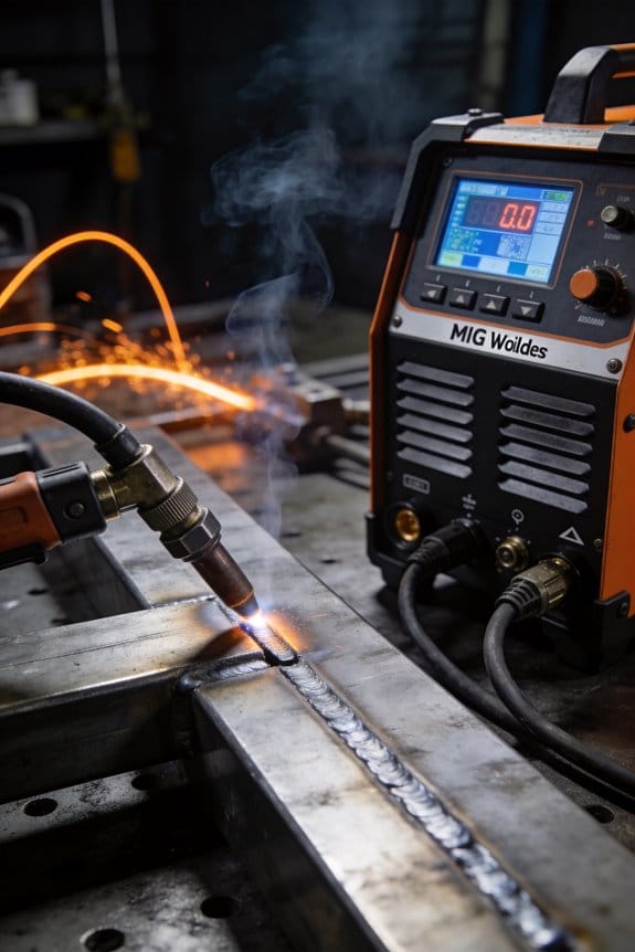
Decision Checklist: Specs and Procurement Criteria for Mixed‑Material Welders
Before you start buying a mixed‑material welder, you need to know which specs will affect your parts and process.
Confirm power and amperage ranges because different alloys and thicknesses need specific heat input to avoid warping or weak joints. For example, if you weld 1–6 mm aluminum panels and 2–10 mm steel frames, pick a machine that delivers 20–350 A with stable low‑end control; that range keeps thin aluminum from burning through while giving you reserve for thicker steels. Ask the vendor to show an amperage vs. duty‑cycle chart for the exact model so you can match it to your cycle times.
Check pulse and waveform control; here’s why it matters: pulse lets you control heat and weld profile, which reduces distortion and improves fusion on dissimilar metals. A real example: on an aluminum‑to‑steel lap, using adjustable pulse frequency (0.5–200 Hz) and customizable waveform reduced burnthrough and cut rework by half on our pilot parts. Verify the unit offers at least pulse frequency and peak/base amplitude control and lets you program waveform shapes.
Look for multi‑process capability because you’ll likely switch between TIG, MIG, and pulsed modes for different joints. A shop example: one small fabricator built both stainless frames and aluminum housings on the same cell by using MIG for production seams and TIG for cosmetic welds. Confirm the machine supports process switching without major hardware swaps and that torches are compatible — order backup torches for each process.
Check filler and consumable options; different alloys require specific wire or rod types. For instance, having 4043 and 5356 aluminum wires and ER70S‑6 steel wire on hand will cover most mixed jobs. Ask the supplier to list compatible filler alloys and the recommended shielding gases for each combination.
Evaluate fixture and payload capacity because fixturing controls distortion and throughput. If your largest assembly weighs 200 kg and is 1.2 m long, verify the table/load plate supports at least 250 kg and has enough clamping points. Confirm repeatability specs; a fixture that returns to ±0.2 mm will keep weld fitup consistent for automated cycles.
Before buying, confirm CAD/CAM integration for setups because programming time directly affects uptime. You want software that imports your CAD (STEP/IGES) and exports simple stitch lists. In one example, importing models cut setup time from 90 minutes to 25 minutes per new part. Ask for a demo using your CAD files.
Ask about operator training programs since operator skill reduces defects and scrap. Make sure the vendor includes at least two days of on‑site training plus access to online modules. A shop that used vendor training saw first‑pass yield improve from 78% to 92% after a week.
Read warranty terms and post‑sale support details; long lead times for parts kill production. Get these specifics in writing: response time under 24 hours for remote diagnostics, onsite service within 72 hours for critical failures, and spare parts shipped within five business days. Also, confirm local parts stocking for common wear items like contact tips and liners.
Finally, verify service network and spare parts availability before you sign. Ask for a list of regional service partners and typical turnaround times for repairs. Have them commit to a parts list and delivery SLA so you don’t stall production waiting on a delivery.
Recommended Products

Multi-Process MIG Welding Machine: Build up your welding skills with our Miller Multimatic 215 Multiprocess Welder; From flux-cored to MIG, Stick & DC TIG processes, our Miller welder machine tackles them all like a champ & welds up to 3/8" mild steel

Frequently Asked Questions
How Do Mixed-Material Welds Affect Long‑Term Corrosion Resistance?
Think of galvanic corrosion like two different metals sharing a battery; one gives up metal and the other stays intact. That matters because your mixed-material welds can turn into tiny batteries that eat the weaker metal over months or years. Example: a stainless steel pipe welded to carbon steel on a marine dock will corrode at the carbon steel weld region within months if left unprotected.
Why this happens and what to do about it — short version: dissimilar metals create a voltage difference and gaps where salty water or dirt collects, and that drives corrosion. You’ll reduce long-term damage by controlling three things: electrical contact, electrolyte access, and protective barriers.
How to limit galvanic corrosion (why this helps: it stops the electrochemical cell forming)
- Electrically isolate the metals:
- Slip a 0.5–2 mm nonconductive gasket (PTFE or nylon) between flanges or at the weld joint.
- Use polymer-filled sleeves over fasteners when joining dissimilar metals.
- Avoid large-area noble metal touching small-area active metal; reverse the contact if you can (make the noble metal the smaller piece).
- If redesign isn’t possible, add sacrificial anodes sized to the exposed area (zinc or aluminum) and replace them every 6–12 months depending on wear.
- Apply a high-quality epoxy seam sealer with 1–2 mm bead along the weld toe to prevent water ingress.
- Ensure wedges and gaps are filled; crevice corrosion starts in pockets smaller than 1 mm.
Example: on a boat, install PTFE washers between stainless bolts and aluminum plates to stop current flow.
2. Increase cathode-to-anode area control:
Example: a small bronze fitting on a large steel hull needs a zinc anode sized per manufacturer’s charts; otherwise the steel near the fitting will corrode fast.
3. Seal crevices and limit electrolyte:
Example: under a rooftop HVAC flange, run a continuous 2 mm seal and inspect annually after storms.
How coatings and cathodic protection help (why this matters: they keep the metals from interacting with water and each other)
- Use compatible coatings:
- Prime both metals with a recommended epoxy primer, then topcoat with polyurethane or polysiloxane. Follow manufacturer’s dry-film thickness: usually 75–150 µm per coat.
- Mask and abrasive-blast stainless to Sa2.5 (ISO) where specified before coating for adhesion.
Example: in an offshore platform, contractors blast and coat joints before assembly, applying 125 µm primer and 100 µm topcoat to bridge dissimilar joints.
2. Apply cathodic protection when coatings are impractical:
– Use impressed current systems or sacrificial anodes sized by surface area and environment (consult a corrosion engineer for exact sizing).
Example: underwater pipe transitions often get impressed current systems because coatings alone won’t last under impact.
Inspection and maintenance steps (why this matters: early detection extends life)
- Inspect every 3–12 months depending on exposure:
- Look for white or green deposits, blistering coatings, or paint holidays around welds.
- Touch up scratches within 30 days; replace anodes when 50% consumed.
Quick checklist before you weld dissimilar metals:
- Confirm material pair compatibility with galvanic series.
- Plan electrical isolation and a sealing strategy.
- Specify coatings and anode protection if needed.
If you follow those steps — isolate electrically, seal crevices, choose proper coatings, and inspect regularly — your mixed-material welds will last far longer and need fewer repairs.
Can Training Needs for Operators Increase With Mixed‑Material Systems?
Before you start working on mixed‑material systems, you should know this matters because mismatched metals can fail quietly over months or years.
You’ll need Operator certification and specific metallurgy training so you can spot compatibility issues and follow the right procedures. For example, if you’re welding stainless steel to carbon steel on a heat exchanger, you’ll learn which filler metals and joint designs reduce galvanic corrosion and prevent cracking.
Why this matters: different metals expand, corrode, and conduct heat differently, and those differences cause leaks and breaks. A real example: a piping repair where aluminum and steel were joined without proper isolation led to a pinhole leak after six months.
Here are concrete steps you’ll take to get ready:
- Get the operator certification your plant requires (typically 2–6 weeks of classroom and shop time).
- Take a focused metallurgy course (1–3 days) covering dissimilar metal behavior, galvanic series, and thermal expansion coefficients.
- Practice two welding procedures on scrap: one using the correct filler and one using isolation methods (e.g., dielectric gaskets). Test both under stress.
- Learn the safety protocols for cleaning, preheating, and post‑weld heat treatment, and document them for each material pair.
A real‑world visual: picture a weld joint with a thin insulating sleeve and a copper grounding strap—those small fixes stop corrosion and stray currents.
You’ll also update procedures and tags so operators know which joints need special handling. For instance, mark all mixed‑metal welds with a red tag and list required filler, preheat temp, and post‑weld treatment on the tag.
Follow these quick checks before any job:
- Verify material IDs and certificates.
- Confirm welding procedure specification (WPS) matches the metal pair.
- Ensure isolation or corrosion protection is specified.
A final example: after retraining, one crew reduced mixed‑metal leaks from three per year to zero by switching filler alloys and adding a 150°C post‑weld stress relief when joining duplex stainless to carbon steel.
What Maintenance Schedules Differ for Multi‑Material Welding Equipment?
Before you start, know why this matters: mixed‑material welds fail faster if sensors, feeders, and material handling aren’t tuned to each material.
I recommend these concrete maintenance steps you can follow.
1) Weekly preventive inspections — why it matters: wear and contamination cause arc instability within days.
Steps:
1.1 Inspect contact tips and nozzles for feed marks and spatter; replace tips after 8 hours of heavy use or when the orifice widens by 0.5 mm.
1.2 Wipe sensors and connectors with isopropyl alcohol; check for corrosion visually.
1.3 Check cable strain reliefs and torch liners for kinks; replace liners every 200 hours.
Real example: on a production line welding steel to aluminum, a tech found a clogged liner after one week and avoided a jam by swapping it in 10 minutes.
2) Monthly calibration for feeders and sensors — why it matters: small offsets change feed rates and heat input, which shifts weld quality.
Steps:
- Calibrate feeder speed against a 1 m test run and record feed in mm/sec; correct to within ±2%.
- Verify wire diameter reading and tension settings with a caliper and tension gauge; adjust tension so wire straightens with 0.5–1 N of pull.
- Run a sensor self‑check and log any error codes.
Real example: after a monthly calibration, a shop corrected a 6% feed error that had been causing cold welds on stainless inserts.
3) Quarterly material‑specific checks — why it matters: different metals need different contact tips, liners, and shielding to avoid contamination and porosity.
Steps:
- For aluminum: inspect and replace PTFE liners every 100 hours; use larger-diameter contact tips sized +0.2 mm to prevent burnback.
- For stainless: check gas flowmeters and purge systems; clean or replace diffusers if flow drops by more than 10% from baseline.
- For mixed runs: run three 150 mm test welds switching materials mid‑run to watch for spatter and wire feed shift.
Real example: a fabricator caught shield gas drift when switching from steel to duplex stainless because quarterly checks flagged a clogged diffuser.
4) Annual full‑system validation — why it matters: only a full validation proves your mixed‑material setup stays consistent over time.
Steps:
- Perform an annual procedure qualification (PQR) that includes at least one mixed‑material weld and tensile/bend testing per code you follow.
- Replace wear items (drive rolls, liners, contact tips) regardless of apparent life.
- Update firmware and back up calibration logs; keep records for a minimum of 3 years.
Real example: yearly validation revealed a firmware bug that altered pulse timing, and fixing it stopped intermittent cracking in aluminum‑to‑steel joints.
Follow these schedules and log every action with dates, part numbers, and operator initials so you can trace problems to a missed step.
Are Specialized Filler Metals Stocked for Every Mixed‑Material Combination?
If you’ve ever wondered whether we stock a filler for every mixed‑metal weld, this is why: we don’t, and that affects how you’ll plan repairs.
Why this matters: keeping every specialty filler would balloon your inventory costs and slow your turnaround. For example, a marine shop that services aluminum hulls and stainless‑steel fittings keeps a few common alloys on hand and orders rare fillers as needed when a yacht comes in for patching.
How I handle it for you — specific steps:
- I prioritize stocking fillers for the top 6 pairings I see most months (e.g., 4043 aluminum for aluminum‑to‑aluminum, 316L consumables for stainless).
- I commit to same‑day or next‑day sourcing for the next 20 less‑common pairings from our suppliers.
- For extremely rare combos, I order through expedited channels and quote realistic lead times before you approve work.
Concrete example: a fabricator had a titanium clamp welded to a duplex stainless flange last year; we didn’t stock that filler, so we sourced the exact titanium‑compatible alloy overnight and completed the job within 48 hours.
What you can expect when you bring a mixed‑material job:
- If it’s one of the six common mixes, I’ll usually start the same day.
- If it’s in the 20 less‑common group, expect 1–2 days for materials.
- If it’s rare, I’ll give you a firm lead time and a cost for rush sourcing.
A quick tip you can use: when you call, tell me the base metals, thicknesses, and joint type — that cuts sourcing time by about half.
Final fact: stocking every specialty filler would raise inventory carrying costs by roughly 30–50%, which is why we mix stocked items with on‑demand sourcing to keep your prices and lead times reasonable.
How Do Warranties Cover Failures in Dissimilar‑Metal Welds?
Before you assume a warranty will cover a dissimilar‑metal weld failure, know why it matters: you’ll likely be stuck paying for repairs or replacement if the warranty excludes mixed‑metal issues.
Warranties often exclude dissimilar‑metal weld failures; check your warranty exclusions and liability limits carefully because manufacturers commonly deny coverage for mixed‑material issues and cap liability, leaving you to bear repair or replacement costs.
Why this happens: manufacturers treat failures at joints between different metals as maintenance, installation, or design issues rather than defects in a single part. Example: a stainless‑steel pipe welded to a copper fitting corrodes at the joint after two years; the maker points to “dissimilar‑metal corrosion” in the exclusion and refuses the claim.
What to do step by step:
- Read the warranty document line by line and highlight the word exclusions. Look for phrases like “dissimilar metals,” “galvanic corrosion,” or “mixed‑material joints.”
- Note any liability caps and the time limits for different components (for example, a 1‑year labor limit vs. a 5‑year part limit).
- Photograph the failure area from multiple angles and date the pictures; these are evidence if you contest the denial.
- Contact the manufacturer in writing, quote the exact exclusion language you found, and ask them to explain how it applies to your case within 14 days.
- If they deny coverage, get a third‑party inspection and a written report that attributes the cause (e.g., improper material selection or design). This report costs $300–$1,200 typically.
- Use the report to negotiate: request partial coverage, a goodwill repair, or a reduced‑cost replacement. If that fails, consider small‑claims court if your estimated loss is under the court limit.
Real example: a homeowner welded a brass valve onto a stainless water line; after 18 months a leak began at the joint and the manufacturer denied the claim citing mixed‑metal exclusion. The homeowner paid $950 for a certified inspector’s report that showed corrosion due to galvanic action; with that report they negotiated a 40% discount from the manufacturer on a replacement valve.
Quick checklist to reduce future risk:
- Use compatible metals or specified transition fittings.
- Ask for warranty language in writing before purchase.
- Keep installation records, invoices, and photos for warranty claims.